
Advanced Environment
Advanced Environment Construction covers many new techniques that will enable the construction of a more detailed environment in idStudio. This page assumes you have a working knowledge of World Edit, as well as understanding of Basic Environment Construction, Familiarity with the toolbars and Menus and browsers and tools windows, as these will be referenced.

1. Getting Started
A little more detailed than the box environment we built in the Basic Environment Construction Tutorial! Don’t worry, every single bit of the above environment is explained below, along with quick shortcuts and techniques on how to achieve it correctly and efficiently.
This tutorial covers a lot of ground and components of idTech 5 environment construction. Most environment geometry in RAGE is completely assembled in another application, such as modo or 3dsMax, then brought into idStudio to add lighting, particles, post processing, and more. This tutorial will take a slightly different approach, as we will be using a combination of Brushes and Models to assemble our geometry. This will teach you how to manipulate Brushes and Models which is a necessary skill required for other operations in idStudio, such as properly adding and adjusting Collision as well as positioning Props and Enemies.
Building an environment as Brushes and Models is completely fine; it’s whatever is best for the game’s pipeline. In the end, all geometry is broken apart in the Build Unique process and reassembled for culling and Megatexture purposes.
There is a lot to cover in this tutorial. To speed things along, a topic will be introduced, discussed, and then an example will be shown on how to accomplish that topic using the methods introduced. The examples are a guideline you can follow to accomplish the exact environment above, but feel free to experiment to learn the tools and methods described and come up with your own environment.
2. Advanced Brush Geometry
We learned a bit about Brush Geometry in the Basic Environment Construction Tutorial. For this tutorial, we will be using brushes to construct our basic geometry, such as floors and walls, and also for other components, such as water and a sky. We will be manipulating brushes in a variety of other ways, too. More information on creating brushes can be viewed here.
Let’s start by making our floor. We will eventually cut this floor brush up to add more detail, but for now, let’s set out to make our floor very simple and basic so we can establish our room size early.
2.1 Grid Snap Settings
Let’s first talk about the Grid Snap Settings in idStudio. By default, idStudio sets the grid to 8 units. We can adjust this in various ways:
- The Grid menu shows all available grid settings and can be adjusted there.
- Keys 1-9 select different grids.
- Left Bracket ([) and Right Bracket (]) cycle through the grids.
The Grid is your friend! It is recommended to keep Snap to Grid on at all times. There really is never a reason to go below a grid specified in the Grid settings.
Set your grid size to 64 units (7 on the keyboard). Make a 1280x384x64 brush starting at 0, 192, 0. Remember, use Shift +Q to display the size and coordinates of a selected brush. Apply a suitable floor material to it.
2.2 Clipper Tool
Next let’s add a bit of detail in the floor by splitting it using the Clipper Tool. This tool is great for splitting brushes or making angular cuts in brushes.
To turn on the Clipper Tool, press “X”. Now a bit of overview:
- Clipper Tool works from point to point, cutting through the selected brush.
- The first LMB click will set the starting point, the next LMB click sets the end point.
- The section highlighted Yellow in the 2D Camera View is the section to keep.
- Pressing Enter keeps the Yellow highlight and deletes the other half.
- Pressing Shift + Enter keeps both halves and splits the brush geometry.
- Pressing Escape exits the Clipper Tool and disregards any cuts.
Select the floor and make a few cuts similar to the image below. The easiest way is to split the brush using Shift + Enter, which keeps both brushes. Apply a different floor texture to the new brushes.

2.3 Texturing Techniques
In the Basic Environment Construction Tutorial, we applied a few materials to our brushes but never did anything to adjust their size or rotation. We briefly mentioned the Surface Inspector (S), which allows you to manipulate the position, rotation, and scale of a material on a brush face.
Depending on the texture you chose, you may have noticed its orientation would probably work better if it were rotated 90 degrees. Select a single top brush face that has the texture on it and press “S” to open the Surface Inspector. Find the Rotate value and click the arrows to rotate the material 90 degrees.
NOTE!: The value in the box is the incremental rotation amount per click.

For the other three top brush faces, let’s introduce a VERY handy shortcut for texturing a brush. First select the remaining three brush faces and hover the mouse over the brush face we just rotated. Now, Middle-Mouse (MMB) Click in the World Camera View and watch the selected brush faces rotate 90 degrees and mimic the first brush face we were hovering over. This shortcut copies the orientation AND material of one brush face and applies it to the other selected faces. Extremely handy!
NOTE!:To copy orientation and material of one brush face and apply it to other selected brush faces, hover over the brush face you want to copy from in the World Camera and Middle-Mouse (MMB) Click.
Let’s create the rest of our brush geometry using the methods and techniques described above.
For the walls, we will be using Models to construct most of our detail. The arches and columns in the first image are Models, but between them we will be using brushes to seal the gaps.
Select a couple brick materials and create the brush geometry shown below. Use a combination of copy + paste (Spacebar), and the Clipping Tool (“X”), to mimic the geometry in the image below. CSG tools (under Selection in the Main Menu) can be used to hollow, subtract, and merge brushes. Click the image to view it in fullsize in a new window.
Note: Toggle Clipper and CSG tools buttons are located on the Radiant Toolbar. (see Toolbars page)

Looking at the first image in the tutorial, notice we have this arch style continuing around the room. Let’s copy + paste this section down this side of the wall. You may need to delete some overlapping brushes if there are any. Also, make sure the wall height from floor to ceiling is now 416 units. Finally, let’s extend the end brushes to match the size of the floor:
Now we will Marquee Select (ALT + Drag) this wall and copy + paste it to the other side. We will need to rotate the duplicated wall using the Rotation/Mirror toolbar buttons:

Select the entire wall, duplicate (Spacebar), then press the z-axis rotate button twice which will rotate the selected items 180 degrees. Feel free to experiment with these buttons, they are VERY handy!
Fill in the two remaining ends with a couple brushes.
Let’s move onto the ceiling!
2.4 Constructing the Sky Lights
In most environments, skies are created by applying a sky material onto a brush in the scene. Sky materials themselves are not sources of light, so light entities are then added to mimic the light from the sky. In this environment, a sky would not be visible, so it is unnecessary to use any sky materials in our scene. We still want the main visual light source to look as if it were coming from the sky, so we will be using light entities later in the tutorial to mimic our sky light.
Looking at the original image, our light from the sky is coming from a circular opening in the ceiling. Just like the archways, our circular opening will be made using Models; however, we will need to fill in the gaps using brushes.
Let’s introduce another handy shortcut to speed up environment construction: Hide/Show shortcuts.
- Pressing “H” while something is selected will hide that object, be it a Brush, Model, or Entity.
- Pressing Shift + H will unhide any hidden objects.
- Ctrl + Shift + H will hide ONLY the unselected, leaving only the selected to work with.
- Alt + I selects the opposite of what is selected.
We are going to build out a small piece of the ceiling, isolate using Hide/Show, then work on that piece and create our opening for the sky light. We will then duplicate this and fill in the rest of the ceiling.
Create a 384x384x32 brush above the walls. In the Front view, center it between an archway. Apply a basic concrete material.
Now isolate this new brush using Ctrl + Shift + H. We will now create the hole in the ceiling for the sky light and any addition details we may want. Feel free to create whatever you want for the ceiling, but try and keep the sky light as we will be using it later!

Now unhide everything using Shift + H and duplicate this piece to finish constructing the ceiling. Look for overlapping brushes and fill in the ends with a couple brushes, just like the walls.
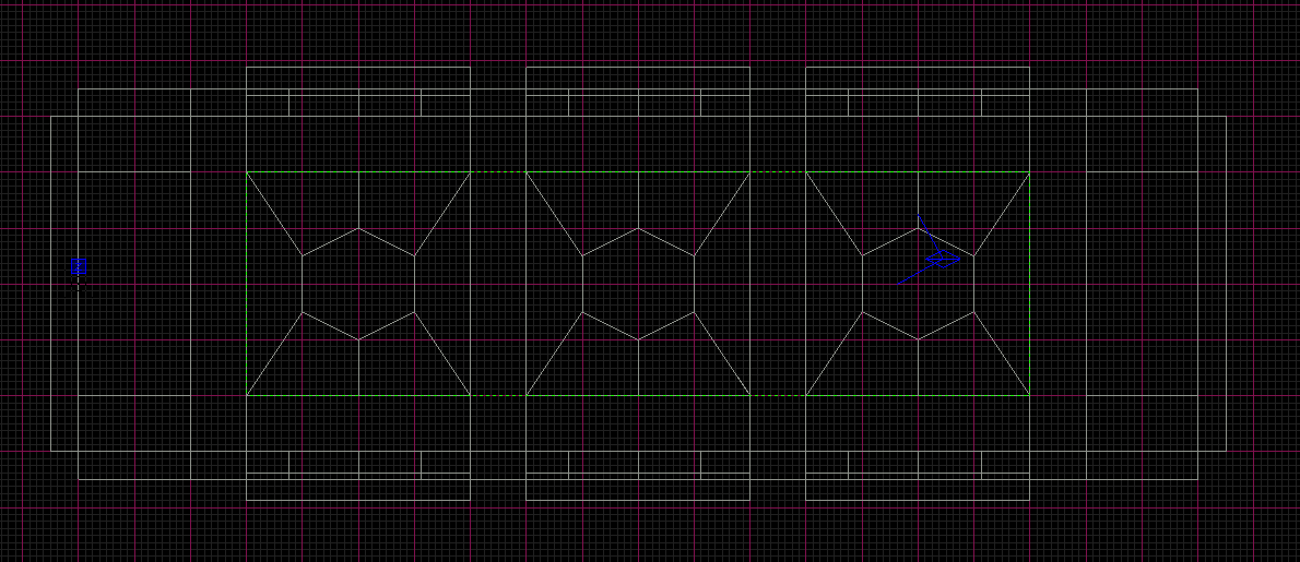
Lastly, make sure that you have a brush over the entire top of the scene to seal the environment and avoid leaks. This brush is highlighted in green in the screenshot below.

2.5 Water Volumes
Adding Water is pretty basic. Since Water is a volume, we will be using a brush to define the Water space.
Let’s first cut out our hole in the floor so we can fill it up with Water. Select the floor brush that is in line with the first set of arches. Using the Clipper Tool, split the brushes accordingly and keep both ends. Lower the middle brush down a bit to create a hole.

Now to create the Water volume. In the newly created hole, create a brush the same size, but only 8 units thick, and lower it below the floor about 16 units. Apply a “common/water” material to it.

With the brush selected, Right-Click and navigate to New Entity > func > dynamicwater. This Brush is now an Entity, but we have to make some minor adjustments to the Entity itself for the Water to behave and look properly in this environment.
Select your new Water volume and press “N” to bring up the Entity Inspector.
In the Entity Inspector you will see several options -
density - 0.004 = water, higher numbers are more dense
viscosity - 1 = water, higher number are thicker
damage- NULL - setting this will apply damage to player per second
material - we used "water/flowingwater"
NOTE: Water will not show up in the rendered 3D Camera View. You will have to wait until we Build and Run in-game.
That’s it for the brush construction. These techniques and shortcuts will definitely help in other aspects of idTech 5, such as creating collision.
We will now be digging even deeper into the environment construction process by adding models, the main components of detail in idTech 5 environments.
3. Placing Models
In idTech 5, there are two types of Model Entities: Static and Dynamic. We will be exploring both in this section.
What is the difference between Static and Dynamic Models? Most of your geometry and environment will consist of Static Models. Static means this Model will never move, and will be Megatextured. Dynamic Models are the opposite; as they are typically not Megatextured, but can be moved in-game or colored through their Entity Properties.
NOTE: Dynamic Models can actually be Megatextured, but typically are not. This is only used if the Dynamic Model needs to be lit exactly the same as the Static World. Remember though, this lighting is baked into that Dynamic Model, so you may run into some undesirable results if that Dynamic Model moves between different areas of lighting.
Let’s start by constructing the rest of our Static Geometry using Models.
3.1 Static
There are a couple ways to add a Model. You can Right-Click and add a New Model or use the Model Browser. The latter is the preferred way, as you can drag and drop into the 2D Camera View and also search through the browser.
Let’s start by adding some Models to our environment, then we will assemble them into place.
First add some arches. Using the Model Browser, search for “brickarch1b” and drag and drop it into the 2D Camera View. Next, add some pillars. We used “brickpillar1b”. The walls inside the arches can be decorated with pipe caps. Search “pipe_bracket” and “pipe_cap1”.
Now, position these Models into their places accordingly. You may need to rotate a few of them using the Rotate/Mirror buttons, found in the Rotate Flip toolbar.
NOTE: Several orientation options, such as Flip, Rotate, and Scale, are also available in the Main Menu of the World Editor under Selection. Another feature found under the Selection Menu is Drop to Ground (Shift + D), which allows you to drop the model either by its Origin or Bounds and orientate it to a surface.

You should have the hang of placing Models now.
Let’s list the remaining Models and show an image of their placement. Click on this image to view it fullsize in a new window. Feel free to be creative! Remember to try different rotations to assemble them correctly.
- “pump1” (models/mapobjects/wellspring/)
- “brickarch1b” (models/mapobjects/well/)
- “stairs1_wide” (models/mapobjects/wellspring/)
- “light1”(models/mapobjects/well/)
- “crate_metal_a” (models/mapobjects/iphone/wasted_garage/)
- “brickpile1_lower” (models/mapobjects/d_industrialcity/)
- “brickpile2c_lower” (models/mapobjects/d_industrialcity/)

We now have our geometry constructed using Brushes and Static Models. Let’s look at converting some of these Static light Models into Dynamic Models so that we can adjust their color settings.
3.2 Dynamic
We won’t be getting too deep into Dynamic Models for this tutorial. All we will be doing is taking a Static Model and converting to a Dynamic, then adjusting its color value. This will give the light models a visual “turned off” look. Remember, these Models DO NOT cast light, only Light Entities do.
Let’s first select one of the end light models on the wall. While this model is selected, Right-Click and select Convert to Dynamic, then press “N” to open the Entity Inspector. Navigate to renderModelInfo > color and Double-Click. This will bring up the Color Picker, allowing us to change the color on the Model. You can also press “K” to bring up the Color Picker. Change the Brightness from 255 to 0. If you were to render now in the 3D Camera View (F3), this light’s color would be black and appear “off”.
NOTE: If the light model was a Static Model, you may still see the color change working in idStudio. However, after a Megatexture had been built, this Static Model would be Megatextured and the color would revert back to default. Remember to convert to Dynamic then change the color!
Now let’s set the color on the remaining lights. How about another shortcut to make things a bit easier?
First, select the last light models at the ends of the environment. Convert them to Dynamic. Now, with all three lights selected, open the Entity Inspector. Select the other light model, the one we just set to 0 brightness. Navigate to renderModelInfo > color, Right-Click, and select Copy to Selected. This will copy the color values we set on the first light model to the other selected light models. This is a VERY handy feature and will definitely be a big part of your workflow working in idStudio.
4. Environment Visuals
We now have all of our geometry in place. We will now focus on adding the next layer of visual detail to our environment. This includes Lighting, Particles, and a Post Processing overlay which will really make the visuals pop.
4.1 Lighting
If you render (F3) in the 3D Camera View, you will obviously notice we cannot see anything! This section digs a bit into Lighting and will introduce a few more features and techniques of Lighting in idTech 5. However, please refer to the Environment Lighting Tutorial for a more detailed tutorial regarding Lighting setups.
Lighting in idTech 5 is all baked into a Megatexture and costs absolutely nothing extra to the renderer. With this in mind, we can really leverage the Lighting in idTech 5 to make the most out of our environments. We can use hundreds or thousands of Light Entities to craft a perfectly lit scene. Great Lighting in idTech 5 is what really makes this renderer stand out from the rest.
Referencing the first image at the beginning of the tutorial, most of that visual quality and atmosphere is coming from Lighting combined with a Post Processing Effect.
Let’s begin by adding some Light Entities that will represent our sky light.
As mentioned in the previous tutorial, to add a Light you Right-Click in the 2D Camera View and select New Light. This will create a default size Light Entity that you can start with. You can, however, specify a size before creating the Light Entity. Simply draw out a brush that will represent your Light Volume, then Right-Click to New Light. Using this method, draw out a 640x640x576 brush in the center of the room and create a Light from it. If you render now, you will finally see your geometry in the environment. But we need to adjust a few things to make it appear correctly as a sky light.

While rendered, press F5 to toggle on Entities in the rendered view. Now select the Light. Notice the pink dot in the center. This is the Origin of the Light and can be moved around to mimic the starting point of a Light, such as a sky light from above. Move the origin up and into the ceiling hole that we cut out for the sky light. Notice the shadows adjust in real-time as you move the origin.
Now we are getting somewhere! But the color of the light doesn’t seem quite right. Let’s adjust that. Change the HSBO (Hue, Saturation, Brightness, Overbright) located in the lightColor property of the entity inspector, to 44, 65, 255, 1.5. Now it looks more like a strong sunlight from above.

Let’s add some Light Entities to the light models we placed before. We used a 256x192x192 sized Light with a HSBO of 0, 0, 255, 1. Duplicate these around the room, along with the sky lights we used before. Remember we “turned off” the end lights in the Dynamic Model section!
We also added a bright light up in the sky light hole to make it appear brighter. We then added a dimmer fill light to simulate a bit of ambient or bounce up at the ceiling. For the sky light fill we used HSBO of 0, 0, 255, 2.8 and the dimmer fill light we used 34, 65, 190, 1. Feel free to experiment with these settings and other lighting techniques.
Duplicate your fill lights to the other two sky lights. Looking good!

Let’s move on to a quick tutorial in Particles.
4.2 Particles
Particles can help bring any environment to life. For this tutorial, we will only be placing Particles into the environment and changing a few values on them.
Referencing the top image once again, notice the light beams coming from the sky lights. These are Particle Entities, and we place them as func_emitters.
Right-Click and add a func_emitter. This is our Particle Entity. We now need to specify which Particle it will emit. Open the Entity Inspector and navigate to particleSystem and Double-Click. This pop-up menu displays all the available Particles to choose from. For this tutorial, let’s select “ambient/mb_lightbeam”.
If you render now, you will notice the Particle emits upward. We need to rotate it to point down, so use the Rotation/Mirror buttons or press “R” to turn Rotation Mode on. Press “R” to toggle it off.
Once that is complete, let’s double the size of our Particle. Navigate to renderModelInfo > scale and change it to 2, 2, 2.
The last thing we need to do is change the color; it’s a little bright! Change the HSBO to 0, 0, 25, 1. Now position the Particle in the three sky lights.

4.3 Post Processing
Next we will add some Post Processing, and we will define it as a volume called an EnvArea. An EnvArea is basically a Light Entity that defines a Post Process.
Simply Right-Click and navigate to New Entity > envarea. Position it in the center of the room and resize it to cover the entire environment. Open the Entity Inspector and change envEffectsDecl to “game/tutorial/env_01”. Render the environment and watch the colors adjust to the Post Processing.
5. Building and Running the Environment
We have everything in place for our new environment. We covered a lot of ground with this tutorial, and we hope it taught you a lot about building an advanced environment in idTech 5. Now to try it out in-game!
Remember from our Basic Environment Construction Tutorial, we need to add a PlayerStart before Building and Running in-game. After doing this, let’s save out the environment to “base/maps/tutorial/advanced.map”.
Now go to Build>Build Wizard. Make sure your map is shown in the "Select Map" dropdown menu, and go ahead and select Full Map Build + Mega Bake for the Build Preset option. Click Build and let the Build process finish. Uh oh… we have an error in our compile. We have a leak!
5.1 Leaks
A Leak is when an environment is not properly sealed and Entities can “leak” out into open void. We can bypass this error by rebuilding using the Map Build Wizard. Select Build-> Build Wizard, and click on the advanced tab. Use Slow Map Build as your Build Preset and under the Build Misc. options, select Build BSP Only + No Flood. However, for a production environment, this is NOT recommended. This is only to be used to help iteration times and quicker workflow while moving Entities around.
When a Leak happens, you will notice a big red line drawing from an Entity to a hole or gap in the environment. Since Models are Entities, they cannot be used to fix a Leak, so let’s hide them by pressing “M” and then following the red line to the Leak. It appears our floor brushes are not properly sealing up the environment. Simply grab the brushes that are causing the leak and extend them to the wall, filling the gap. You should be able to rebuild using Build> Full Map Build + Mega Build, and your build should complete with no errors.
When finished, click the Engine tab next to the World Edit tab and press the Tilde “`” key to bring down the console. Here, we will first specify “slowmap” then the path and name of the environment we just saved.
slowmap tutorial/advanced
In the next tutorial, we will be covering the process of stamping on Megatextures. In order to build a megatexture for your map, you will need to perform a Full Map Build + Mega Bake without errors, which can be found in the Main Menu under Build.