VGA monitors accept three analog colour signals in the range of 0 to 0.7V. While Altera's UP1 boards have a built-in VGA connection, the Excalibur development boards do not. Using a few more pins and a couple of resistors 8bpp (256 color) VGA output can be easily produced.
Typical 8bpp systems use a 3-3-2 bit distribution: 3 bits for red, 3 for green and 2 for blue. Other breakdowns are possible. This design is based on a 3.3V VDD which is available from the expansion headers on the Nios board. The schematic is shown below:
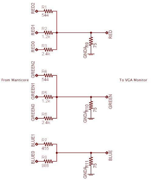
Each of the outputs, RED0-2, GREEN0-2 and BLUE0-1 originate from the chip and must pass through a 3.3V buffer before reaching this circuit.
For a single 3 bit colour the required digital to analog conversion should be:
| Binary Value | Analog Value |
|---|---|
| 000 | 0.0V |
| 001 | 0.1V |
| 010 | 0.2V |
| 011 | 0.3V |
| 100 | 0.4V |
| 101 | 0.5V |
| 110 | 0.6V |
| 111 | 0.7V |
The 100Ω resistor was chosen somewhat arbitrarily. It is half of the voltage divider formed by the other three resistors. If it is too small currents in the may exceed maximum ratings, and if it is too large the current may become disturbed by noise. Using the three cases when only one pin is active, the value of each resistor is determined using the following equations:
In general, given a 3.3V supply the output voltage of the voltage divider is:
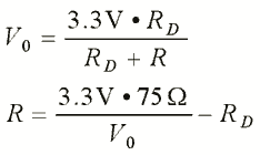
Where Vo is the analog voltage desired for the given binary value.
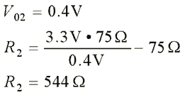
For the most significant bit:
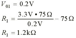
And for the next bit:
And for the last bit:
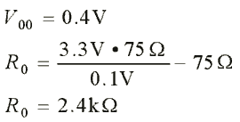
For 2 bit colour, the desired conversion is:
| Binary Value | Analog Value |
|---|---|
| 00 | 0.0V |
| 01 | 0.233V |
| 10 | 0.466V |
| 11 | 0.7V |
The following two equations were used. For the MSB:
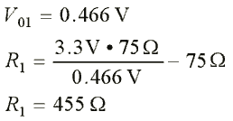
And for the last bit:
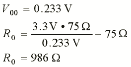
This method can be adapted to a 5V output expansion slot as well.