Whoa, there:
I forgot to mention: I have a Patreon! Mostly I make fun software, tools to build games, and port games to Linux. If you like those things, please throw in a buck.
Arcade1Up mod!
If you missed them, I previous wrote up these other Arcade1Up cabinet mods:
- Wire up stock volume and power switches to the Raspberry Pi
- Run stereo speakers into the marquee
- Trim down a massive rom set to exactly what you want
So after two weeks, I never quite got the stock volume switch exactly where I wanted it. Sometimes it was too loud, sometimes it was too quiet, and there was no base level on anything: different cores, different games, and even different preview videos had different volume levels, so I was constantly moving the switch back and forth, never really happy with the final volume level. I adjusted the amp and the values in the monitor program, and it just wasn't ever perfect for me in all situations. You really need more than "mute," "normal," and "loud" settings. It would be nice to have really fine-grained control over the volume from moment to moment.
If only there were already an analog dial that controls the audio gain somewhere in the cabinet...!
What I want to do is replace the stock volume switch in the cabinet outright, with the volume dial on the amp. While I could probably mount the entire amp's faceplate in the top of the control panel, that's a little ugly and unnecessary. It would definitely be easier, though! Because bad news: this mod doesn't just need soldering, it needs desoldering, too. This isn't ninja-level hard, but if you've never done this before, you should definitely practice first, watch a few YouTube videos about it, and expect to maybe destroy your amp by accident. 17 bucks plus shipping is the cost of a really good education in electrical engineering, though!
I have soldered things a few times before, but I am not a good solderer. So don't look to me for great advice about this, but I'll try to stumble you through this while experts cringe in the background.
First things first: if you had my arcade1up-volume-gpio program from a previous post running at startup, you should remove it from /etc/rc.local first and reboot, so it doesn't try to change the system volume anymore. Then adjust the system volume in EmulationStation's settings to 100%, so it isn't reducing the gain unnecessarily, and quit out so this setting definitely gets saved somewhere. Shutdown the Pi and unplug everything from their power outlets. If you had the volume switch wired to GPIO pins on the Pi, unplug those, too.
I'm working with the exact amp that ETAPrime had in his video:
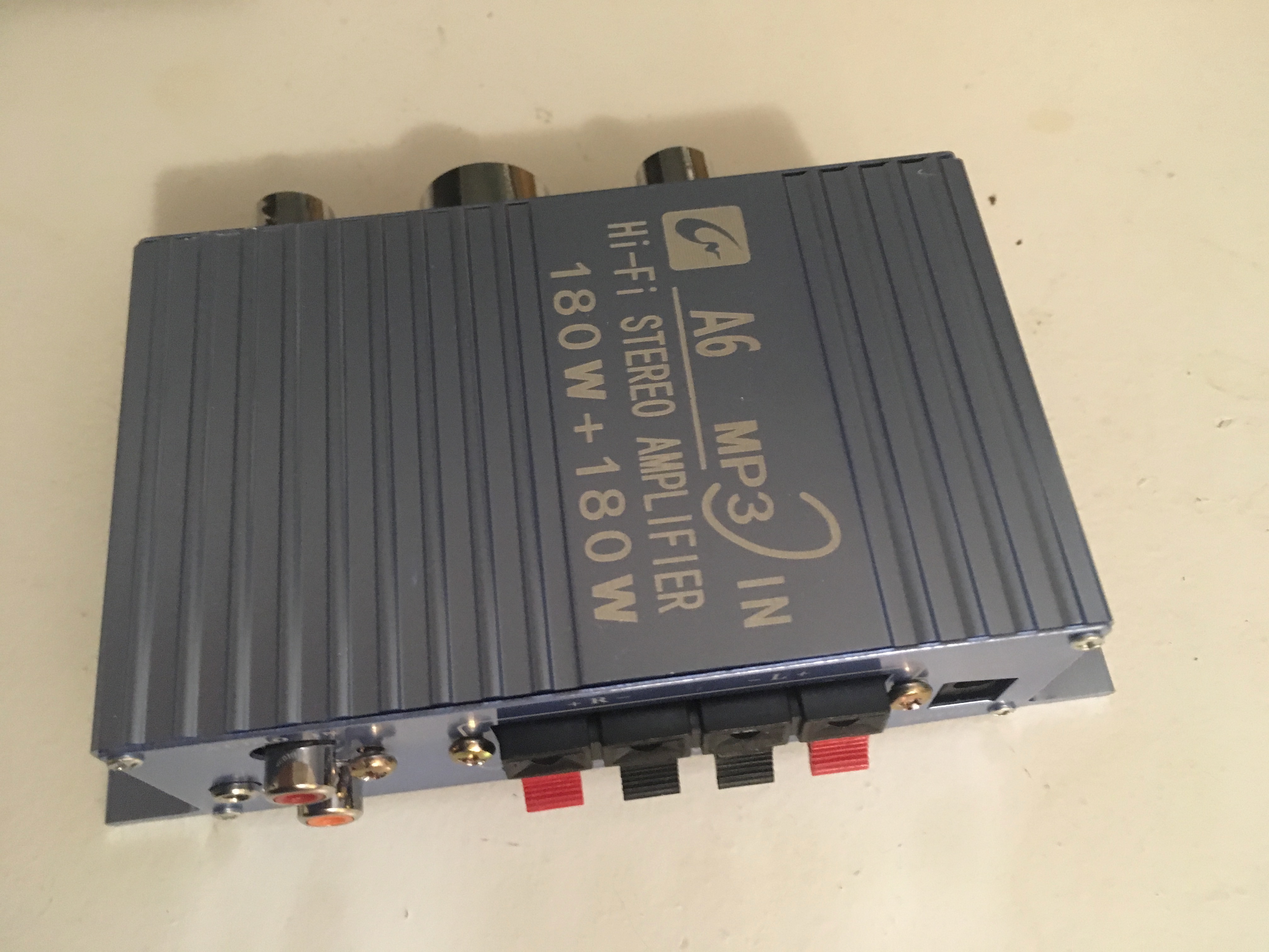
Which I bought from Atomic Market on Amazon. YMMV if you have a different amp, but the basic idea is always the same here.
Let's get right down to the butchery. Take the four tiny screws out of the corners of the amp's front panel, the three screws out of the bottom, and the three screws out of the middle of the back panel. You can leave the back panel's corner screws in for now. Once all those screws are out, you can slide the guts of the amp out of the front:
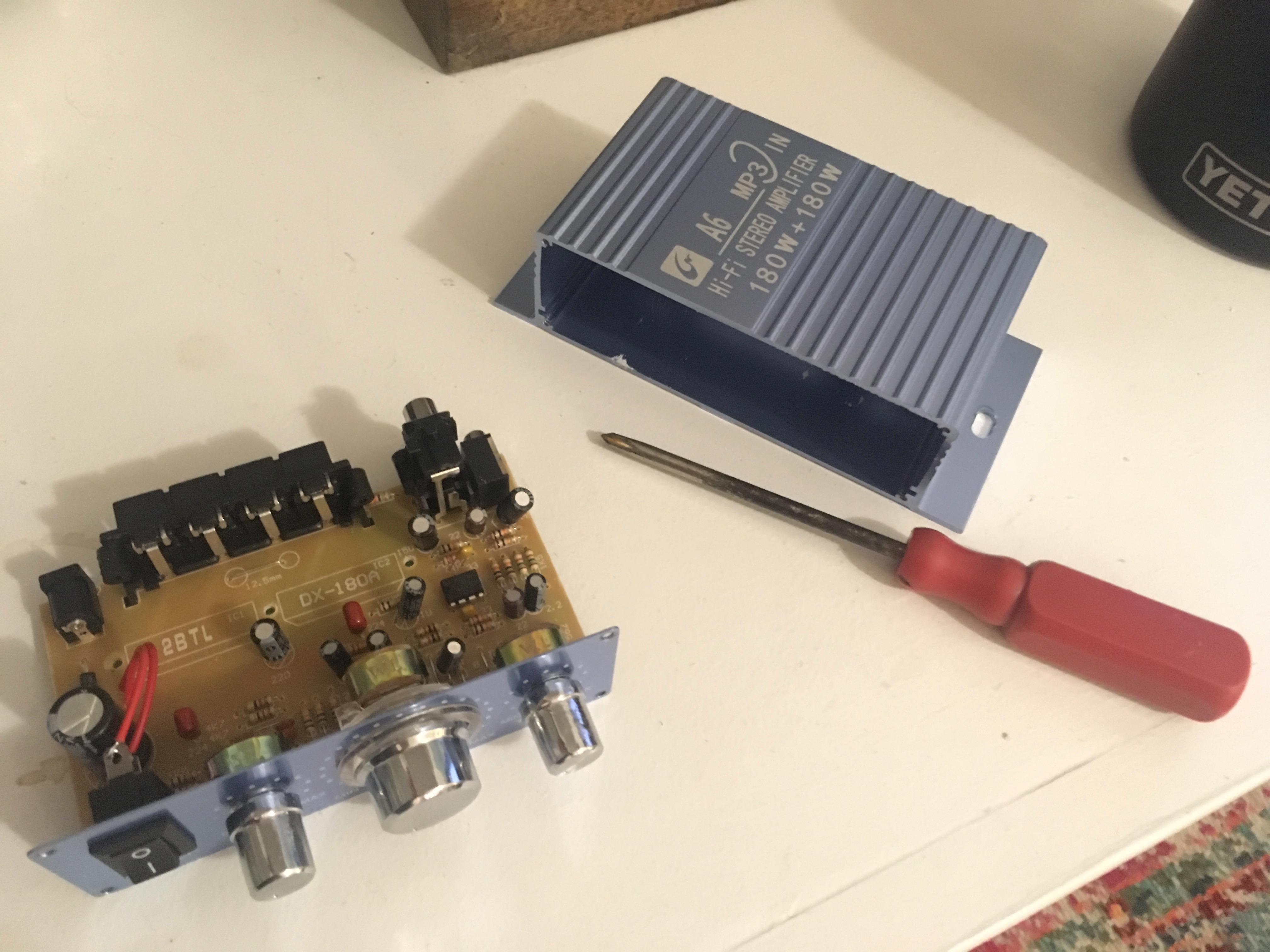
That was the easy part.
Looking at this board, you can see a round gold thingey right behind the big middle dial. That's the thing that adjusts the gain: your volume control. We need to get this off the board.
Pull the plastic cap of the knob off. It should come off without a fight, leaving a metal screw looking thing underneath. That screw has a nut on it under that plastic, which you can twist with a pair of pliers, if not your fingers. It won't give you a fight either. Once that's off, you can pull the clear plastic casing off. Don't lose the nut or the washers, since you'll be reassembling this later. Now comes the hard part.
If you flip this board over, you can see six dots of solder that live right under the round gold thingey on the other side:
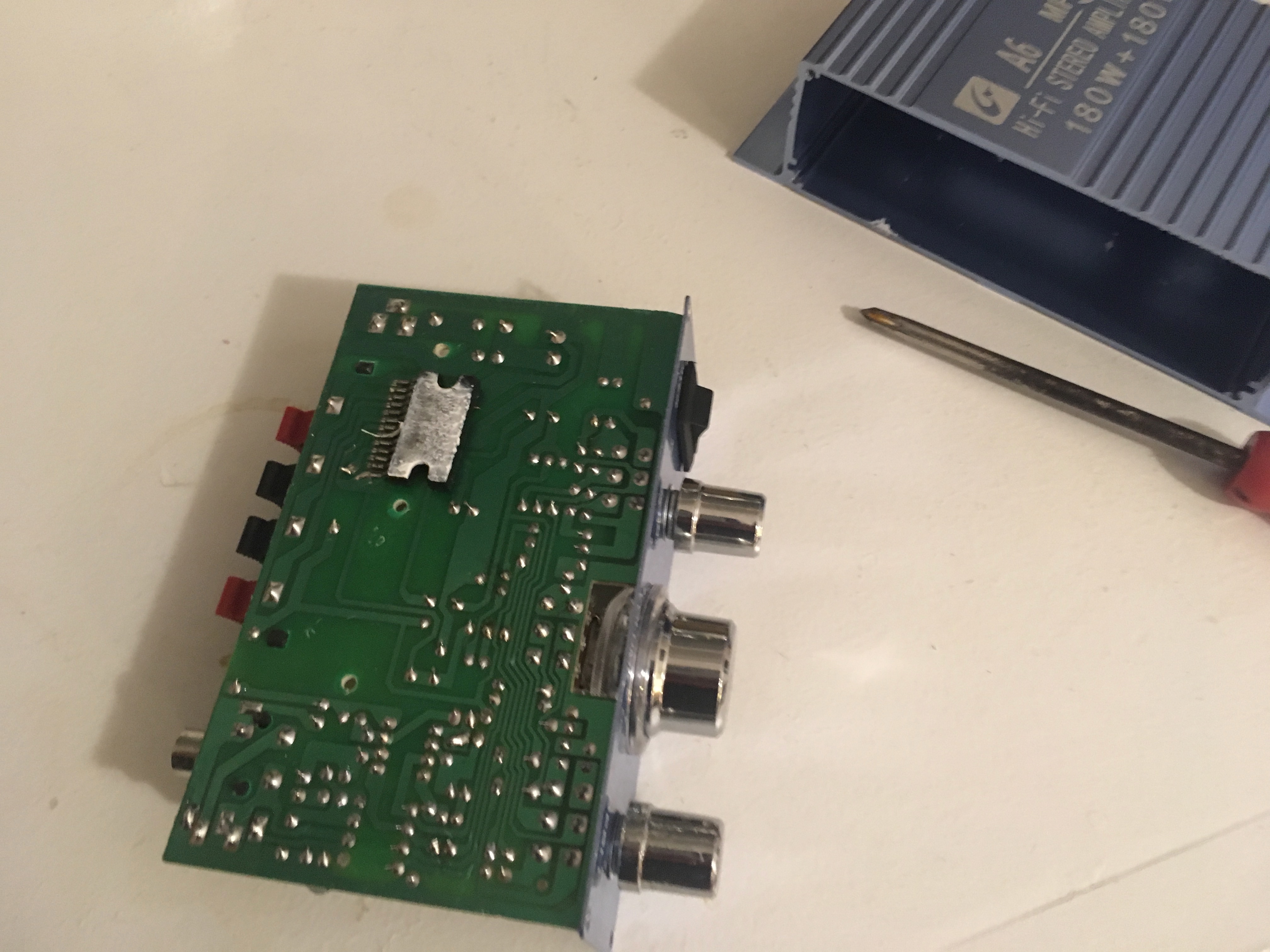
That's what's holding the entire mechanism to the board. The volume control has six metal pins, being held in place by the globs of solder.
There are lots of ways to desolder, but here's what I did. With the plastic bits of the knob removed, I could use the metal screw part as a lever. I applied gentle pressure to that, pushing it away from the board. As I did, I started applying the soldering iron to the 3 globs of solder closest to the edge of the board. As the solder melts, I'd move on to the next one as fast as I could. After I did all three, I'd start over, trying to keep these all hot at the same time, always applying pressure, until the pressure I was applying would make the pins start to slide out of the board. It took a few times, the pins sliding a little more each time until they all popped out together. It was sort of exciting; you could feel the whole thing move as you make a little progress each time. Once those pins were out, I stuck a screwdriver under the round gold thingey, and rested the other end of it on the round gold thingey of the bass control, so I could use it as a lever to apply pressure to the back pins. WATCH OUT for that capacitor right next to the pins, as it looks easy to pop that off by accident! I desoldered the back pins the same way, until the whole mechanism came off:
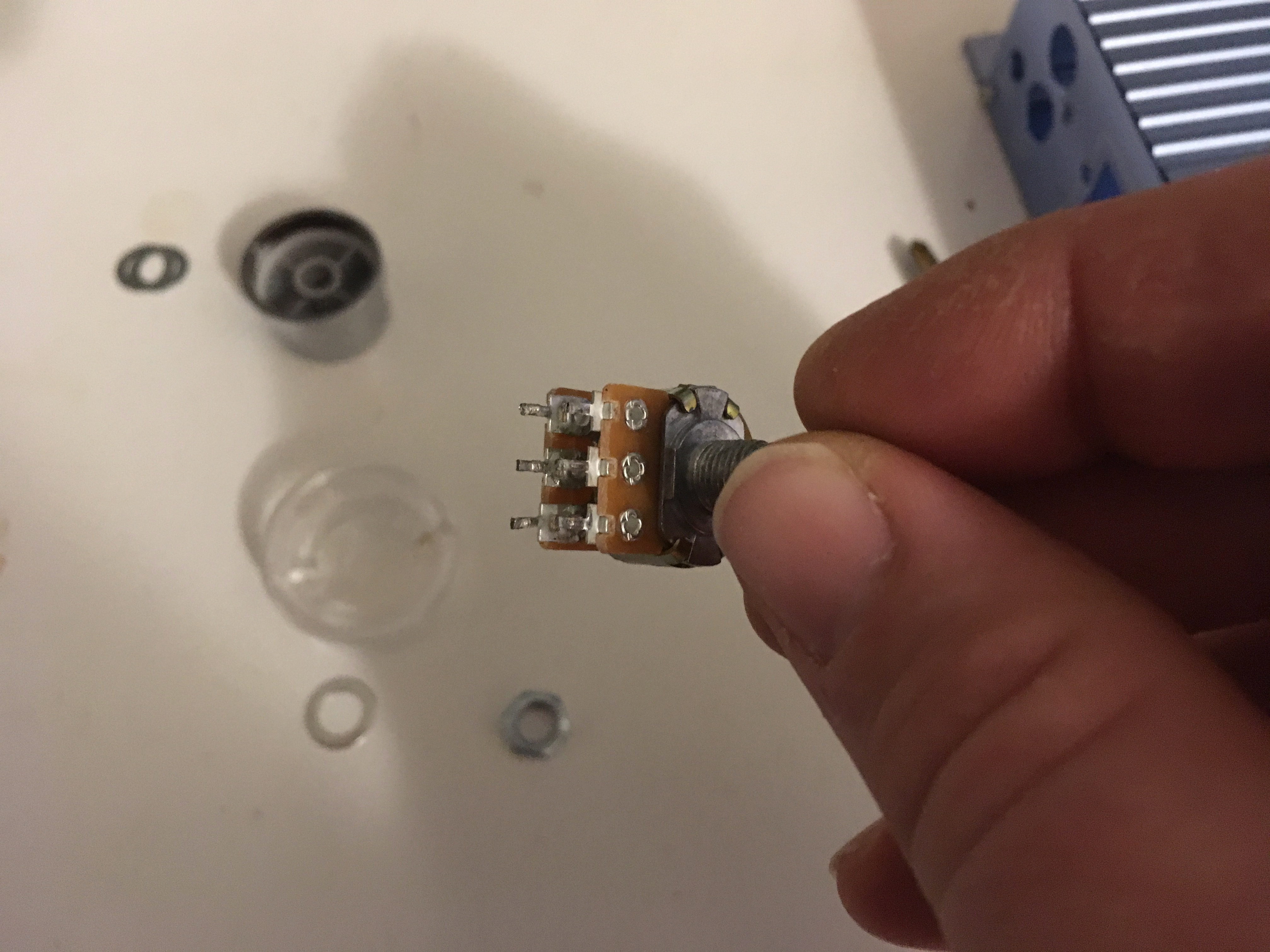
Now we're committed!
This is what my desoldered board looked like:
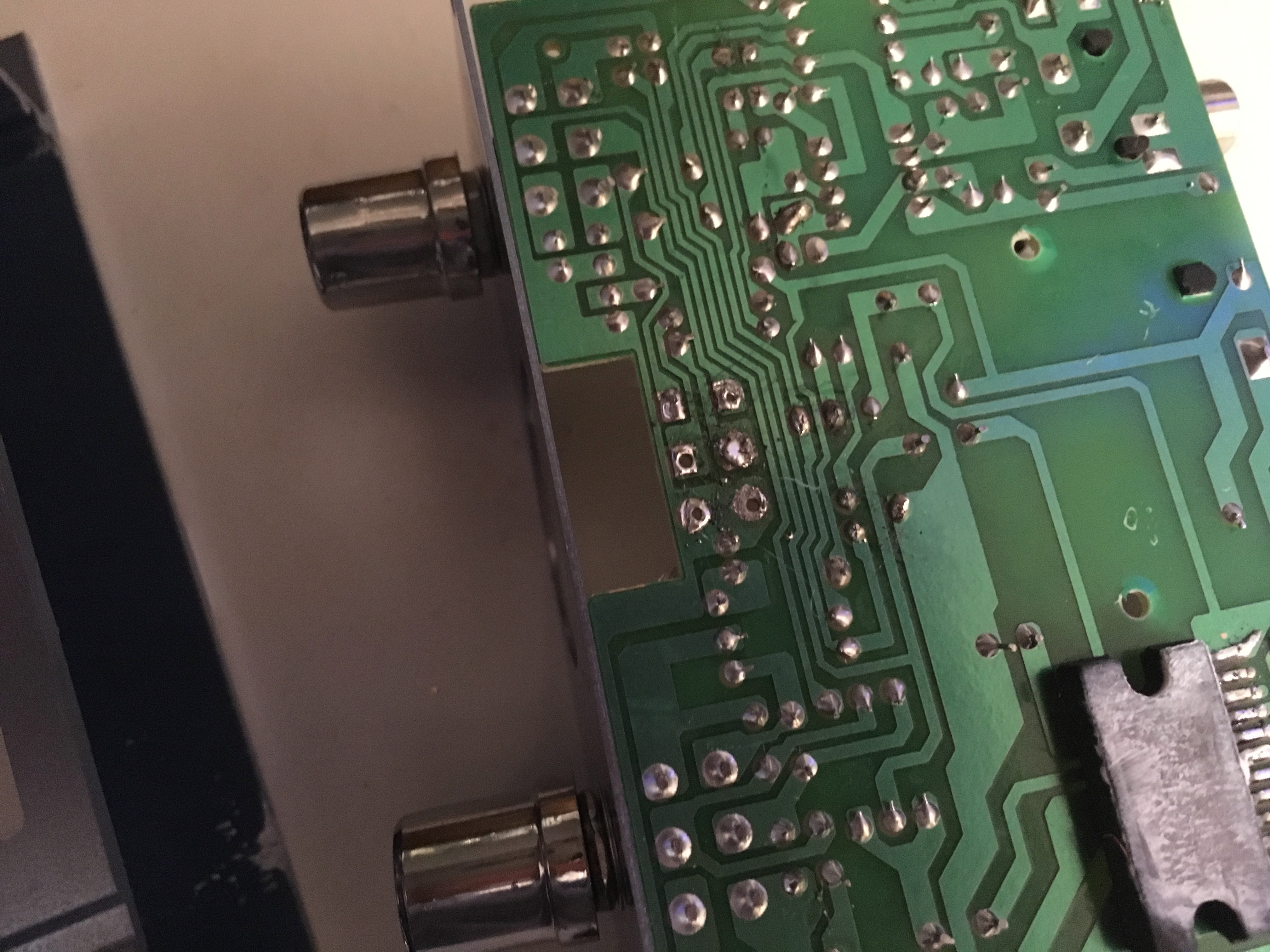
I post this so you can see that I scratched and burned the shit out of this thing. I told you I'm not good at this! But: it still works. If you feel like you fucked up, keep going, because it might be okay. If nothing else, you're getting practice before you get a cheap replacement unit.
The top side looks cleaner than you might expect:
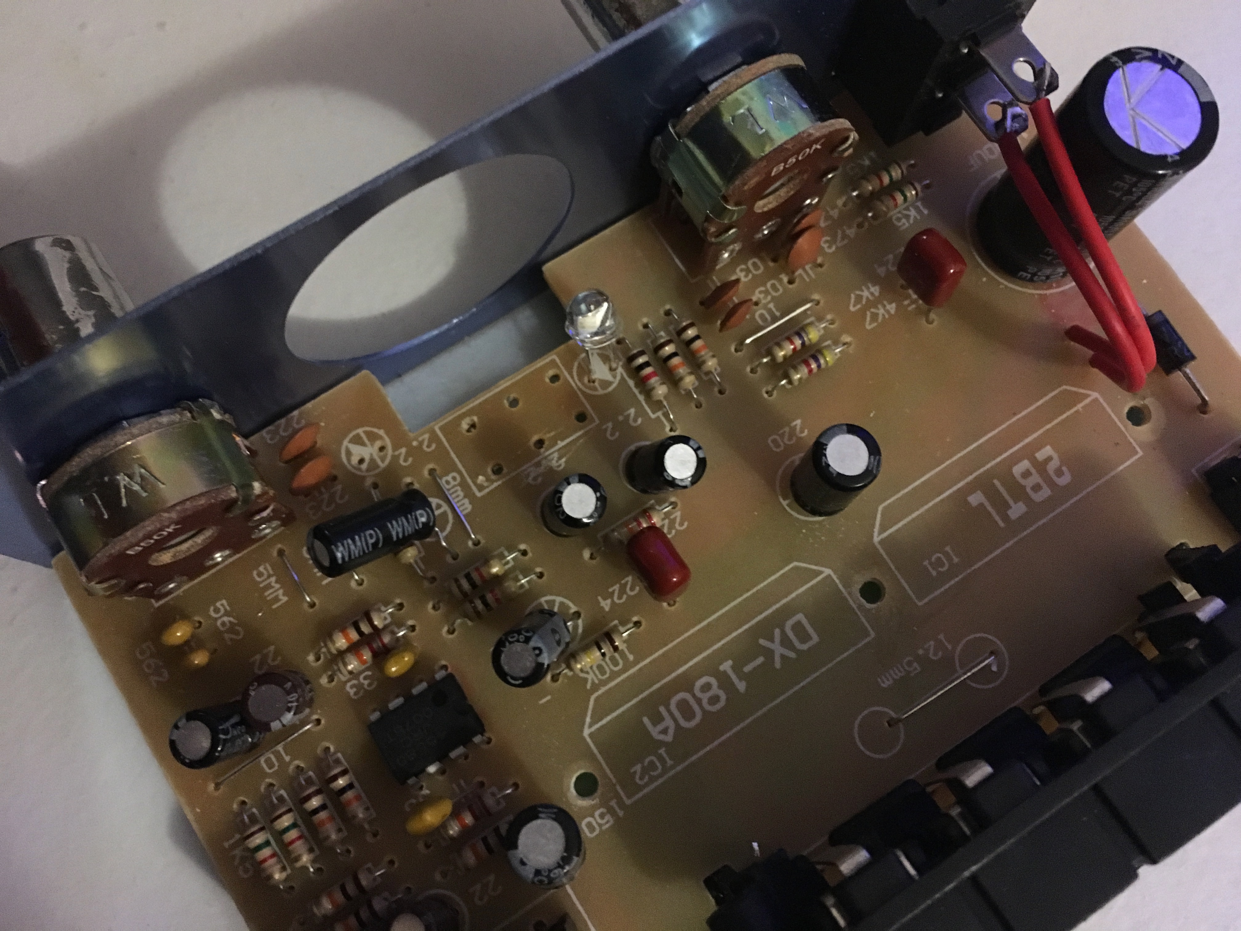
Just a few scratches from my prying screwdriver, but nothing serious.
Now we're going to put some wire in here. I didn't have any left over from previous projects, so I scavenged from elsewhere: the amp is going to move higher up in the cabinet, so I stole large lengths from the speakers I put in the marquee, and obviously I don't need the old volume switch's wires anymore, so they got recycled here too. Ideally you just have a fresh spool of unused wire so you aren't splicing runs together like I was, though! I originally had a spool of 25 feet from Adafruit, and at this moment wished I had two.
So I don't know what each of those six pins on the volume control do--it's possible four of them are useless, but they all appear to have circuitry running to them on the board, so we'll hook them all up. All we need to know about this is that some amount of current was maybe running through these pins directly from the board, and if that same current happens to be running through these pins from the board over a length of wire, then fine, it's the same thing.
So take a bit of wire, strip off the sheath, and put it through the hole in the top of the board. Heat up the existing solder around it so it holds it in place. If there's not enough solder there, add some of your own. All you want to do is make sure that wire is going to stay put. Once it's good and solid, clip off any extra that's sticking though the board. Make sure your solder doesn't connect two circuits on the board. In soldering, less is more.
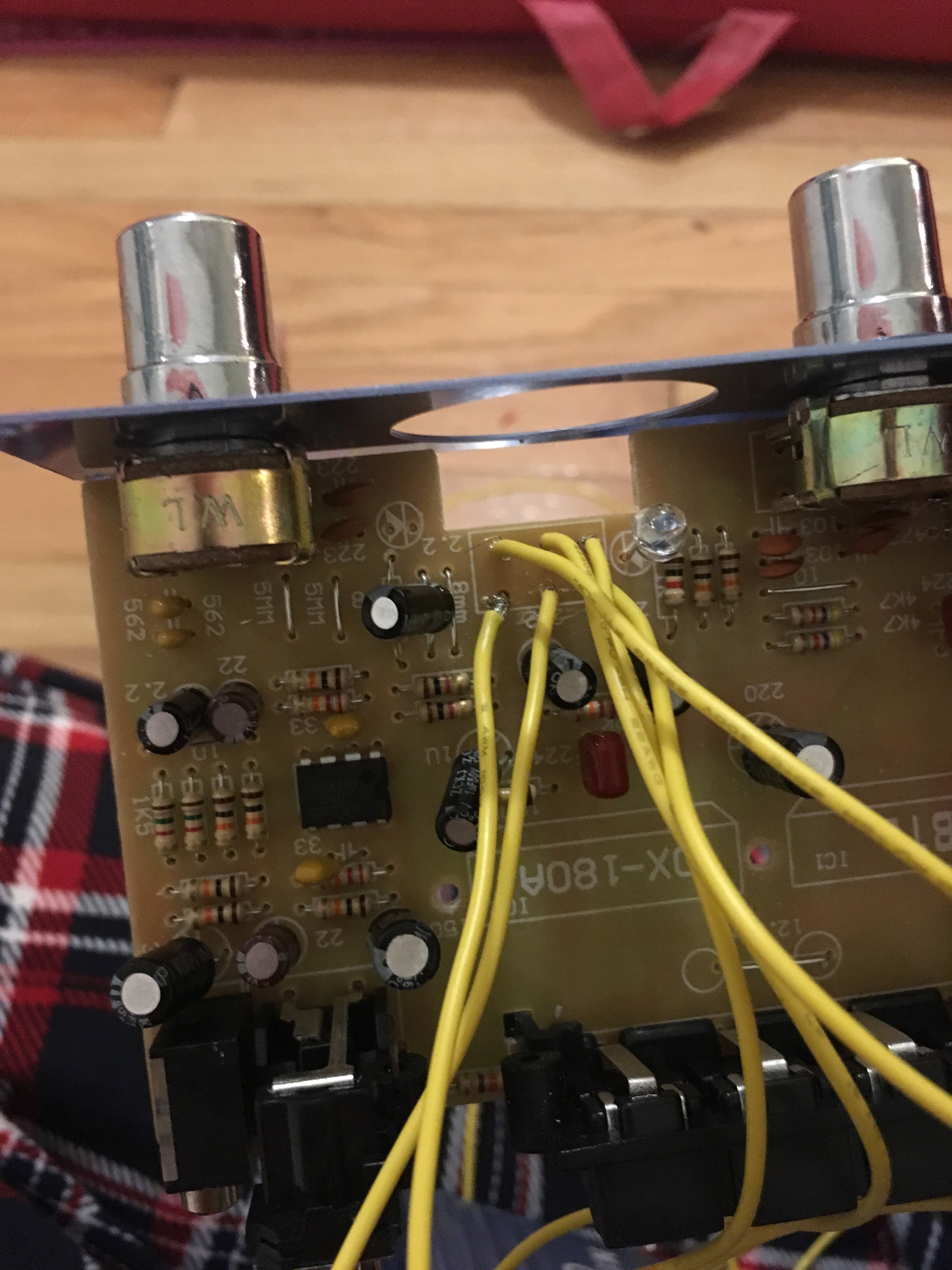
At this point, you can either feed those wires through the hole where the dial used to be, or take your step bit that you've been using to add button holes to the cabinet's control panel and make an extra hole in the back of the amp, which is probably cleaner:
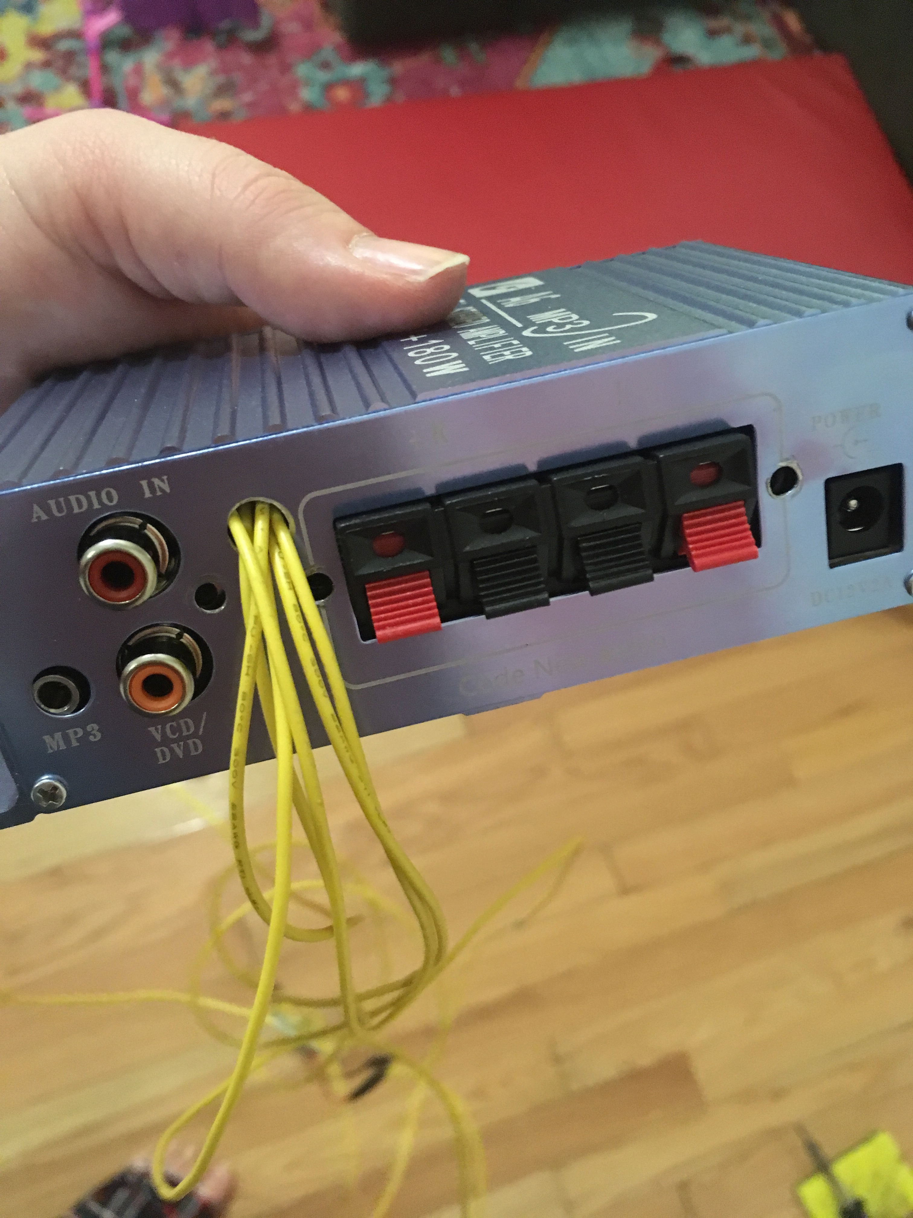
(ProTip: after you drill metal with a step bit, gently drill it from the other side a little, and it'll nicely clean off all those rough metal shavings.)
Now you can reconnect the volume knob. Make sure each wire connects to the pin that originally went in that wire's hole. For testing purposes, you can just wrap some wire through the holes at the tops of the pins, but you'll probably need to solder these on before you're done, to make sure they all hold tight and don't touch another pin.
Now while this Frankenstein's Monster is dangling loose, go ahead and plug everything into it and see what happens:
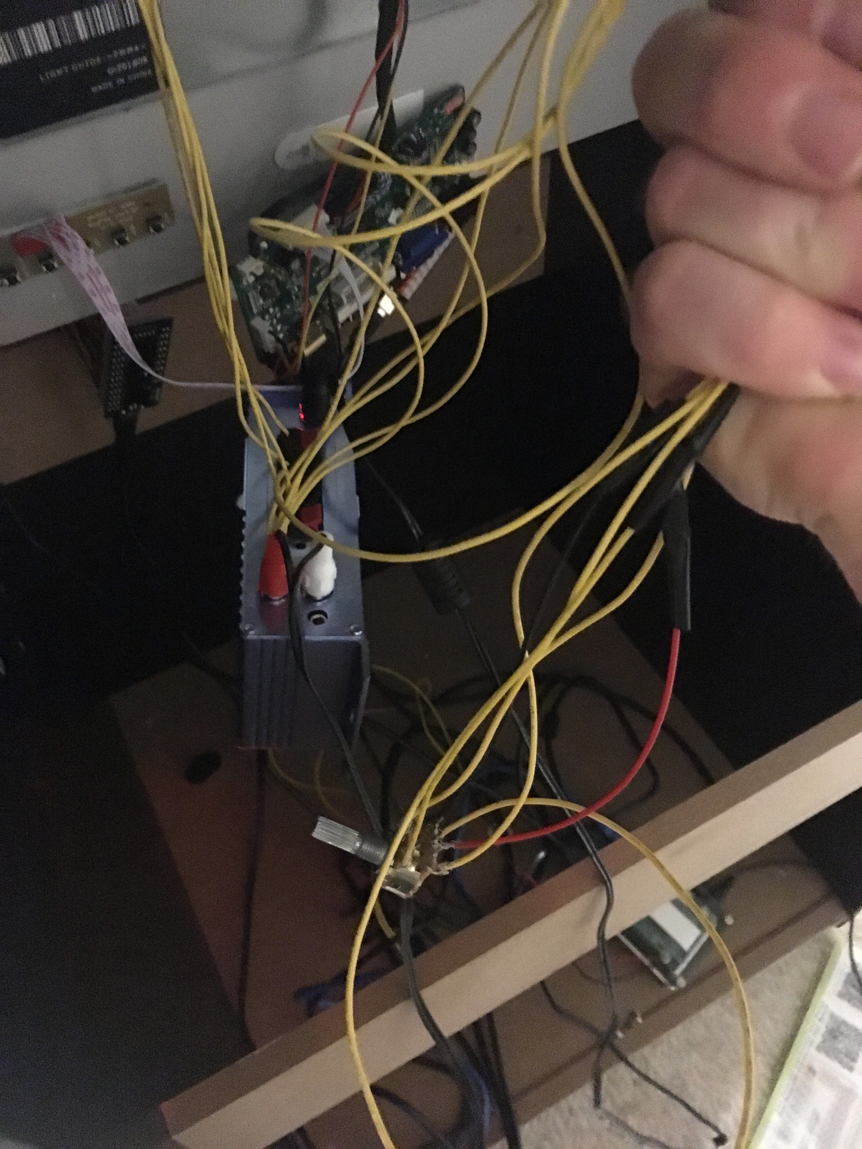
Speakers, power, and the RCA cables; the headphone jack plugged into my phone, playing "Don't Stop Me Now" by Queen, because at this point with the soldering iron? That's why they call me Mr. Fahrenheit!
Turn the dial's screw and see if the volume changes. If it did, congratulations, you didn't destroy the hardware! You can go ahead and seal up the amp's case again now and mount it to the inside of the cabinet. I placed it so it wouldn't be hard to access if for some reason I wanted to mess with the treble, bass, or power controls, but honestly? My hope is to never touch this part again. But I totally dig the ominous red glow coming from the box!
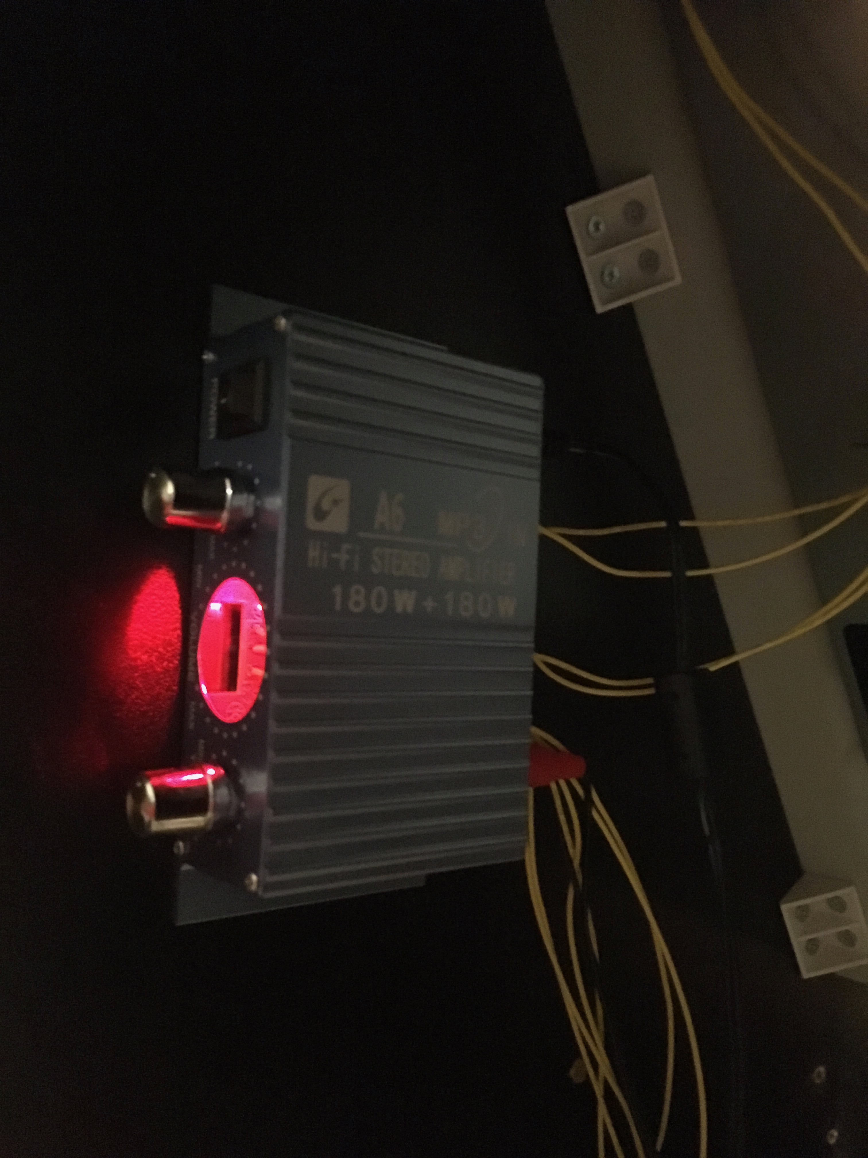
Now let's destroy the original volume switch.
Take off the control panel. Underneath is a piece of plastic covering the power and volume switches. Take out the three screws holding the plastic in place and it will come right out. The plastic your fingers touch when using the switches from above will probably fall off. Don't lose the power switch's plastic, but the volume switch's can go in the trash.
There's a little plastic ring where the switches poke through the control panel:
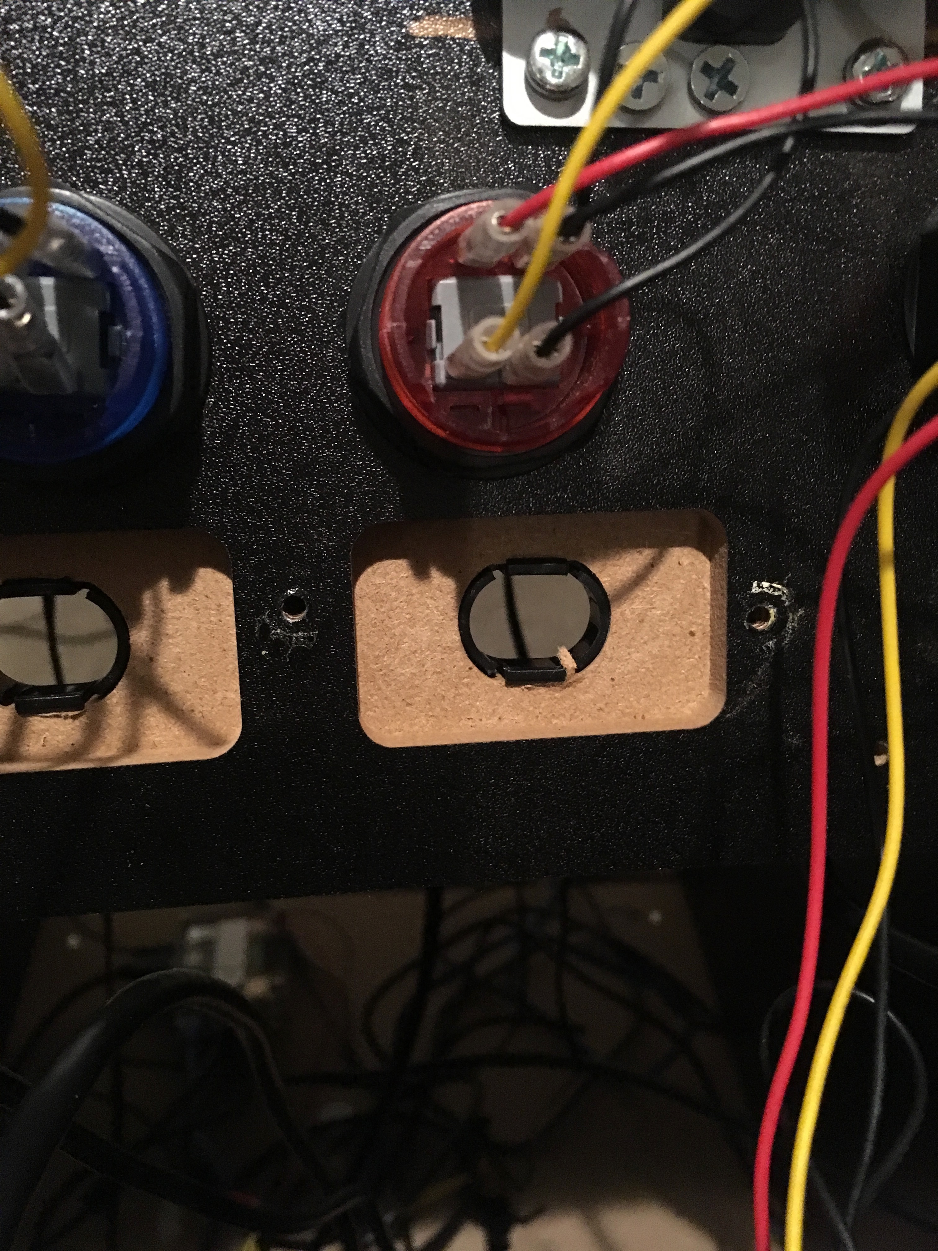
Get under the one on the right (the volume) with a flathead screwdriver, and pop it out. This also goes into the trash can.
The plastic with the three screws that holds the switches from underneath? Cut it in half, so the power switch gets to keep two screw holes and the volume switch area doesn't get any coverage at all:
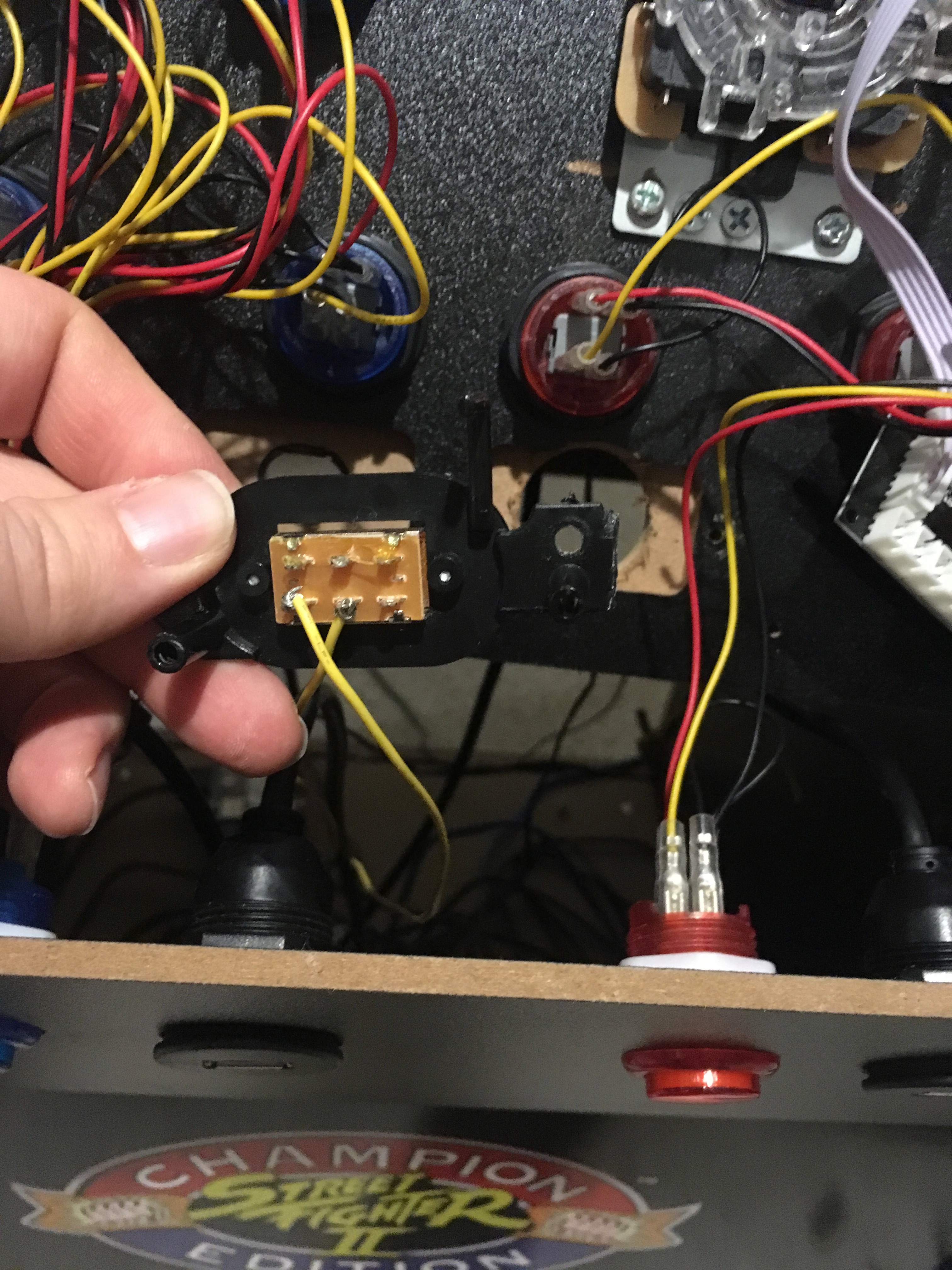
The physical volume switch and its associated plastic can go in the trash. You can reassemble the power switch at this point. Put the plastic cap back on it, and put two of your three screws back in.
Now take your step bit and drill out the original hole. Be careful, because you don't have much clearance between the Player 2 button and the "-VOL+" text, and you'll need most of it.
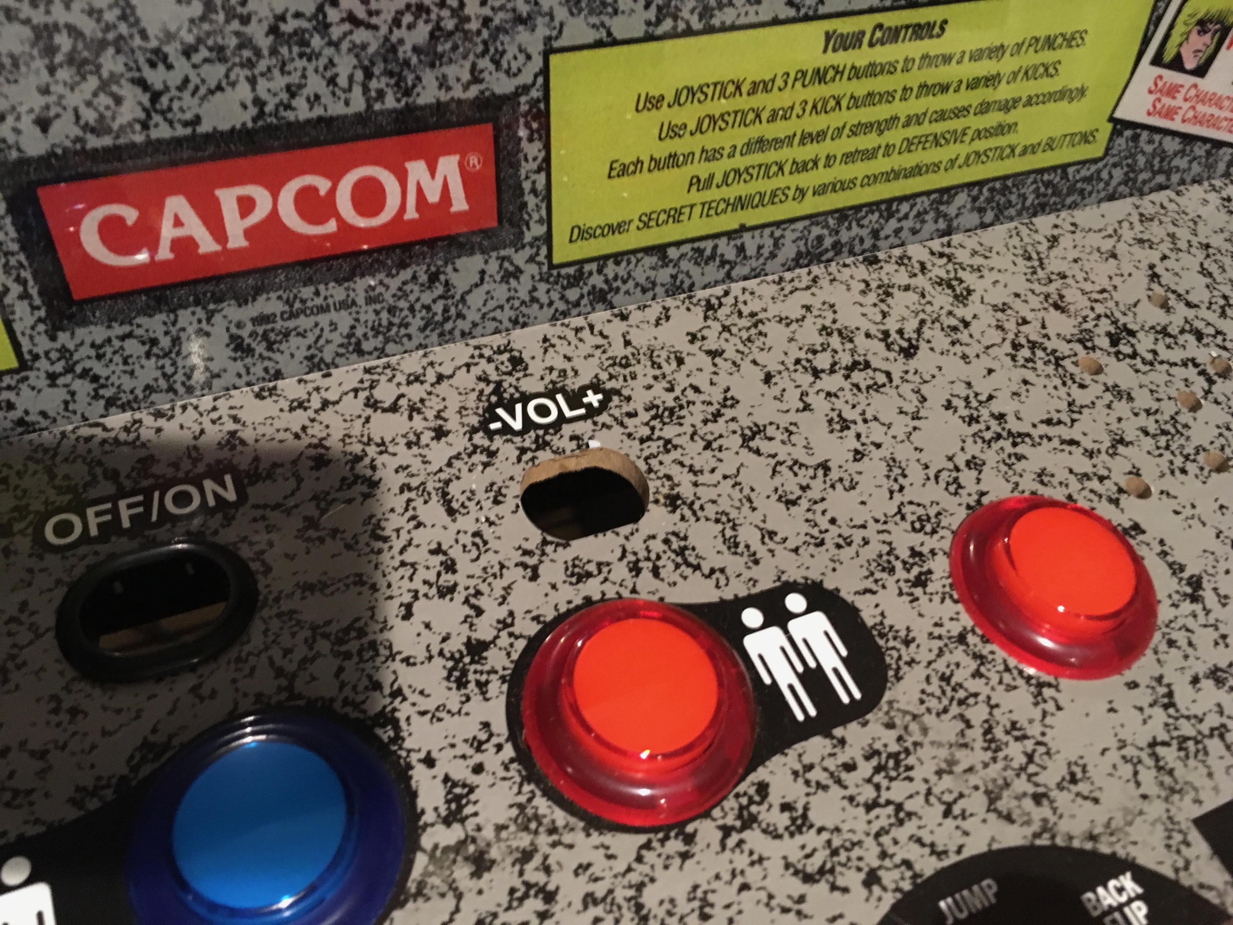
(As you probably know, drilling this board makes an obscene amount of dust. In a perfect world, you do this outside with everything stripped off the panel, or you can just do it on the carpet with everything in place, with your dinner in a bowl underneath the work like I did because I'm too smart to live.)
Go slowly and keep checking if your amp's volume knob casing fits before you drill further. Eventually it will...
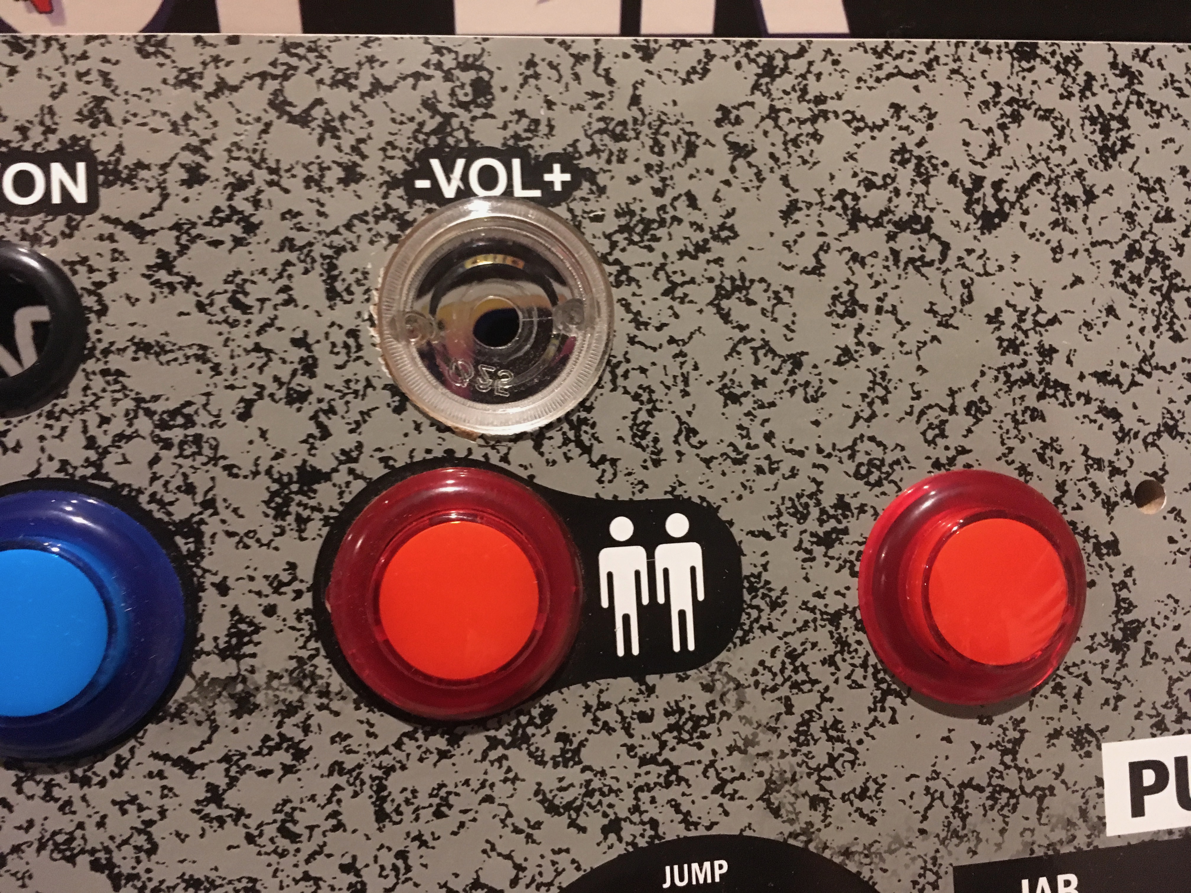
...and then you can run the actual control into this casing, reassembling with the washers and nut from the start that you definitely didn't lose, right?!
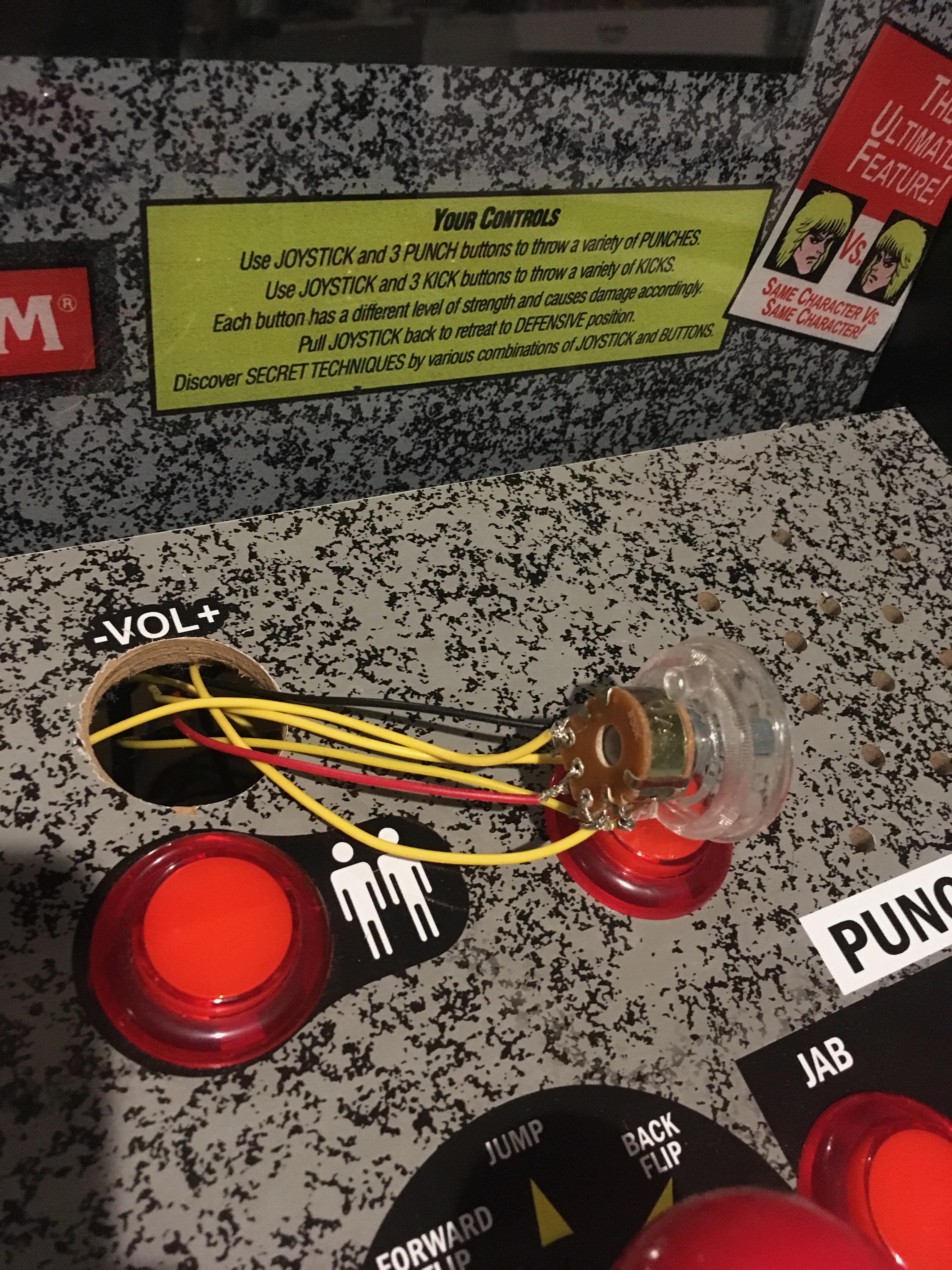
Now you are going to want to glue that casing into the hole, because nothing is holding it in place; we don't have a big plastic nut to tighten on it like ETAPrime's replacement arcade buttons have.
After that, there's nothing to do but put the knob's cap back on and plug everything back in to make sure it still works.
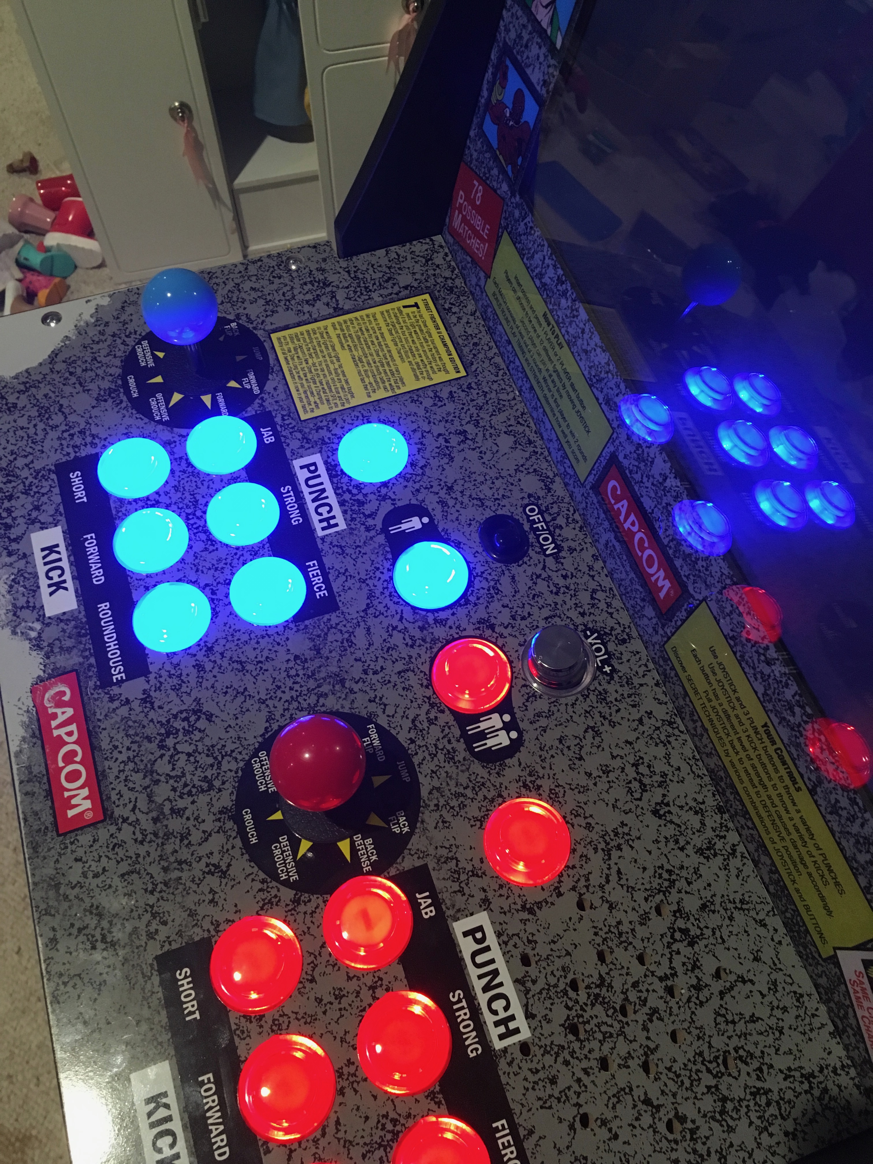
Now you have a fine-grained volume control, conveniently placed, and no dead and abandoned switches on the control panel. And, you probably feel like a total boss for having completed this mod!
--ryan.