Oh yeah, I'm keeping the .plan file alive in 2019. Living the dream!
I got one of those crazy Arcade1Up cabinets for Christmas, and I've been doing all the usual mods.
Naturally I watched the same video from ETAPrime that everyone else did. This got me as far as having a Raspberry Pi wired up and pretty lit up buttons. But since ETAPrime didn't bother with the power and volume switches, almost everyone else seems to ignore them too.
Which is weird, because they're easy to hook up.
I figured this stuff out from experimenting and finding scraps of info on the internet, but I was surprised this didn't land in the pile of common knowledge that gets tossed around discussion forums. How did people get more comfortable with using a step bit drill to add buttons than wiring up a few connectors without solder?
So here's the deal, so this is documented somewhere that people can find it.
Disclaimer
I am not an electrical engineer. I know just enough to destroy things and electrocute myself. Hopefully the subreddit will let you know if any of this is a terrible idea, but this worked for me. I will probably use some technical term incorrectly, or present the basic physics of electricity incorrectly. Plan accordingly.
I did this with a Raspberry Pi 3B (not 3B+). Earlier ones might have differences in terms of GPIO pins, etc...but honestly: upgrade your Pi already if you're still on a 2 or earlier.
I have a Street Fighter II cabinet, because oh my god, how do you not want something with all those buttons for making a RetroPie cabinet?
Power Switch
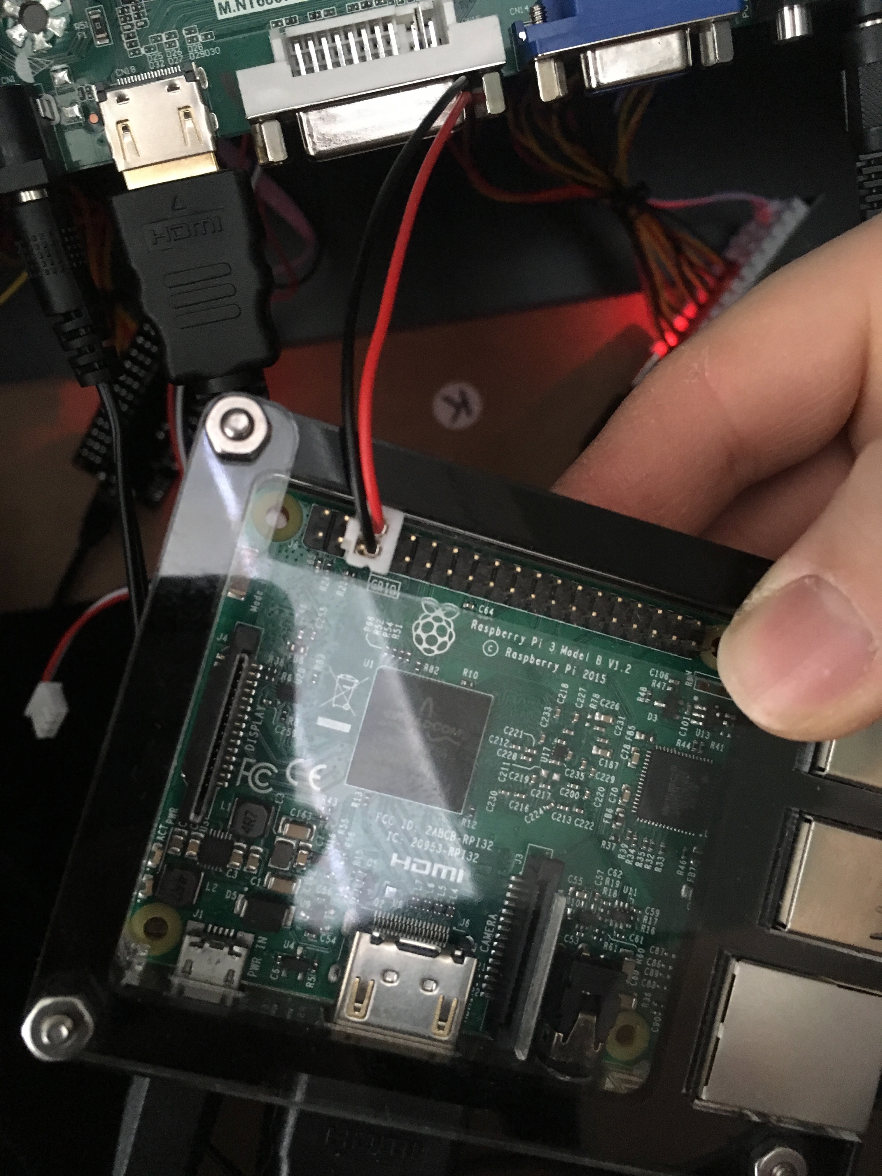
Here's the power switch that came with the cabinet, looking at it from under the control board:
Try not to be horrified that my Pi is dangling from the end of its wires in this shot. Maybe don't do that.
So basically the switch completes a circuit between the red and black wire when in the On position, and doesn't when in the Off position. This is as basic as it gets. So we want to use the switch to tell the system to turn off when you flip the switch to Off, and turn on when flipped to On.
Some people have used a Smart Power thing to get Alexa or Google Home or their mom to turn off the hardware when they yell at it, but that seems silly to me when the switch is RIGHT THERE. It's very satisfying to use during a rage quit.
So (at least on the RPi 3), there are magic GPIO pins that exist just for the purpose of turning the Pi on and off if you want to wire a switch to it, because these Arcade1Up units aren't the first time someone has asked about doing that.
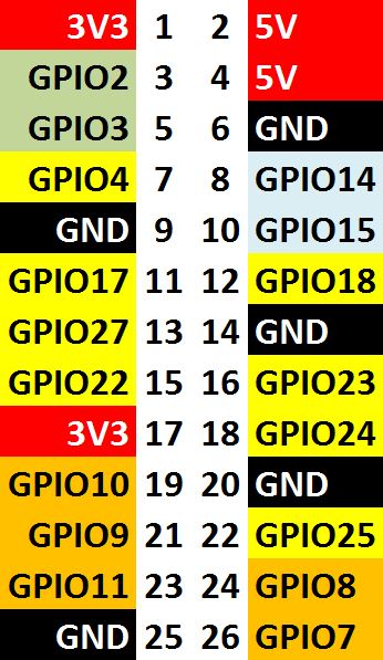
All you have to do is raise a signal (is that the term?) on the fifth GPIO pin, which is confusingly called "GPIO3".
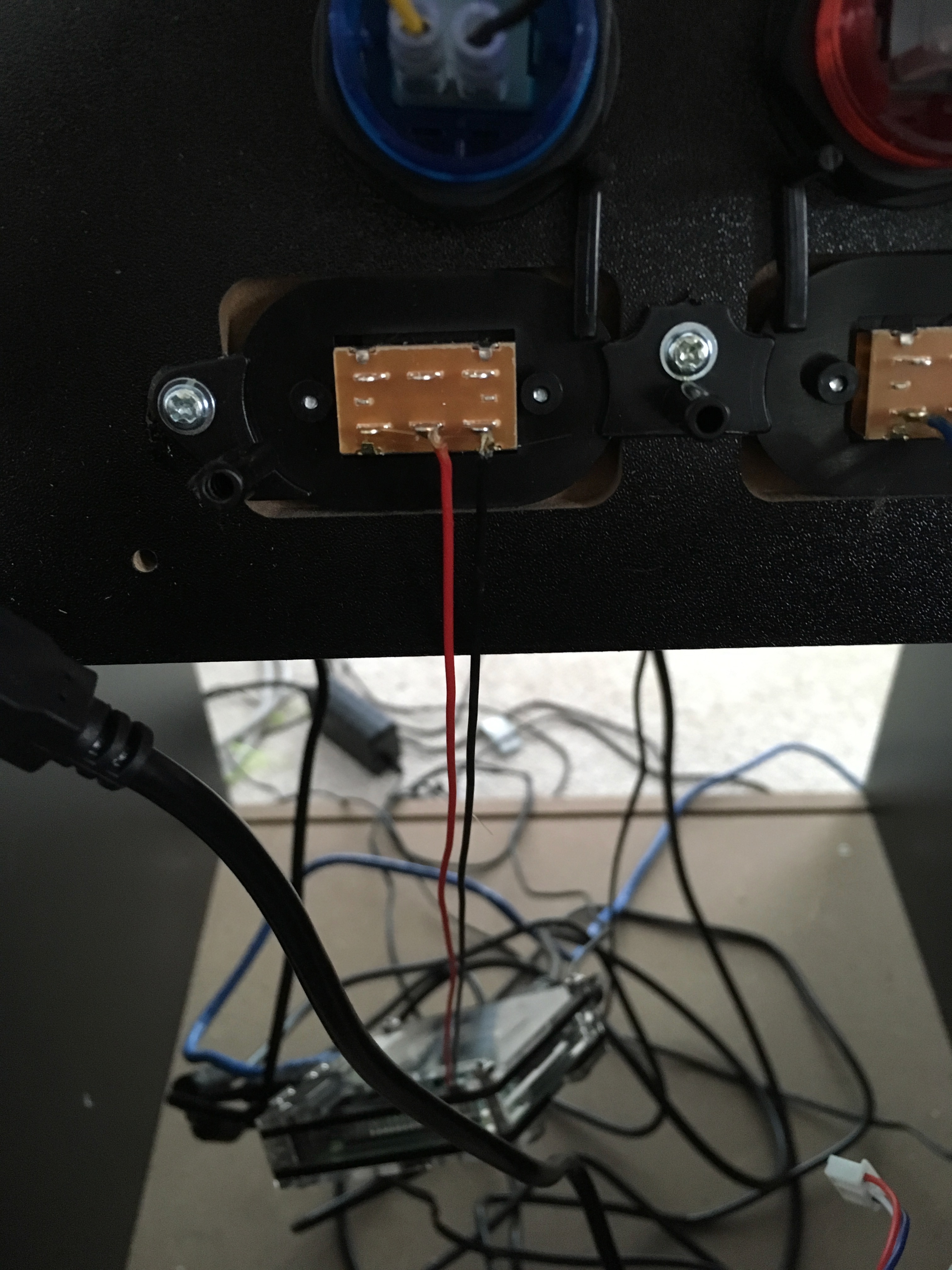
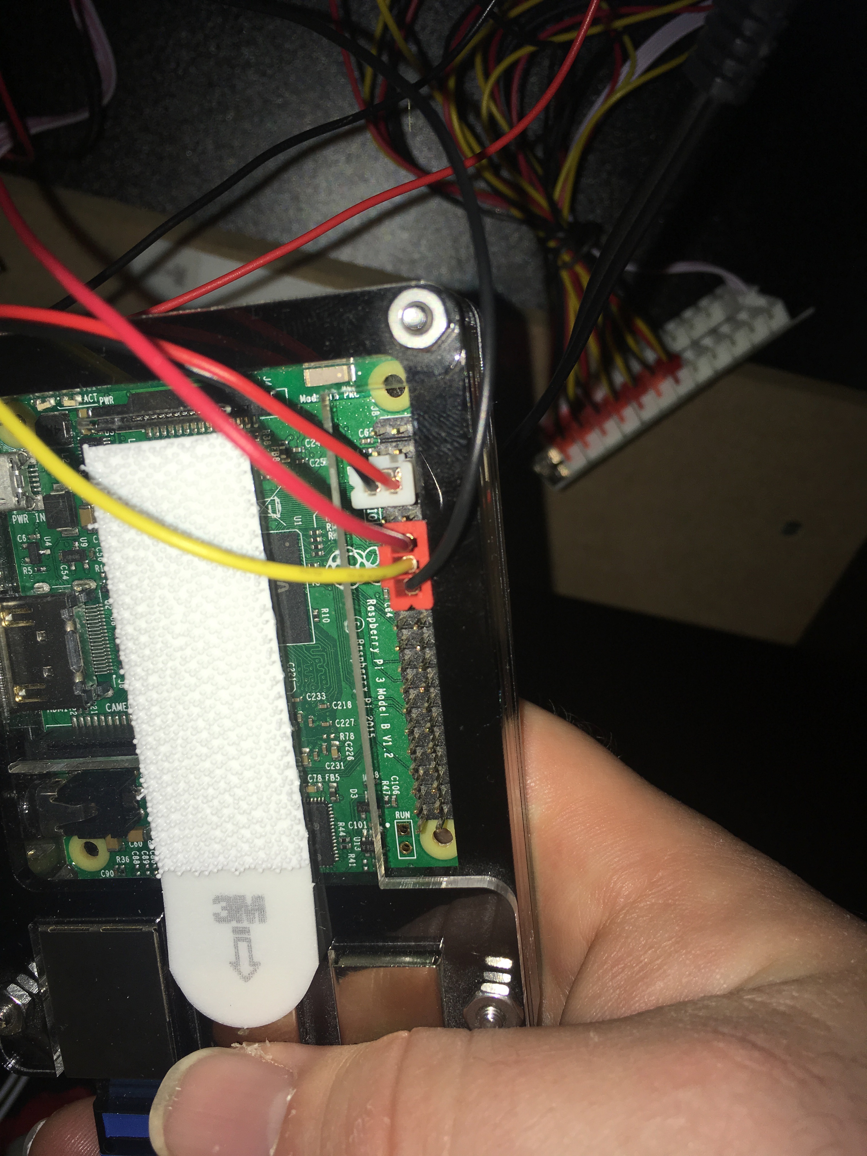
Good news: you don't have to solder anything, so don't get nervous. All you have to do is take that connector that you pulled off the original control panel circuitry and plug it into the Pi's GPIO pins:
MAKE SURE you plug this into the right thing: the pins RIGHT NEXT to this are there to supply current, and will absolutely destroy your Pi when you bridge it into GPIO2. Count out the pins and get the right one. Double check before you reconnect the power!
The red wire goes to the edge of the Pi and the black wire goes to the center, because that eliminates the chance you're going to bump that 5V current pin (that side of the connector is 100% plastic), but otherwise, we just need a simple circuit here and it doesn't really matter which way you wire it up.
Now, here's the hard part. On your Pi, go edit /boot/config.txt and add this line at the end...
dtoverlay=gpio-shutdown
...save and reboot.
(Note that this needs the latest stable release of RetroPie, or maybe just the latest Raspbian, to work.)
Now flipping that switch will cause the circuit to complete, alerting whatever the heck dtoverlay is that the GPIO pin has power. In this case, it sees power flowing through that circuit as a signal to shutdown the Pi, like you had called "shutdown -h now". If you did this right, you'll watch EmulationStation vanish to the Linux console, a little standard shutdowny style things will print and the Pi will halt. The screen will complain there's no signal for a few seconds and also turn off. The amp will continue to amplify silence.
I should say at this point that all of these things still have power, so if you were looking to have everything turn off Off OFF, this is not the solution to your problem, and you'll probably need to get fancier (some sort of IoT power switch, or whatever). But I don't unplug my microwave because its clock is drawing power even when I'm not cooking, and I think about the cabinet the same way. The Pi and display are in standby mode, and the amp is still drawing as much power as it always does, but this does not feel like the end of the world to me.
Standby mode is useful, in any case: the reason we used that GPIO pin specifically is because the Pi3 will notice, even when halted, when that circuit breaks, and treat it as a signal to reboot from the halted state. And once rebooting starts, the display will also turn back on!
This work is already done. Just flip the power switch back the other direction and watch the magic.
There's only one problem: unlike literally every other power switch in the universe, a completed circuit is used to signal that we want the cabinet to turn off, not on. Which means the cabinet's UI is backwards:

On is off and Off is on. :(
So let's fix that! :)
Underneath the control panel, the power and volume switches have a plastic case around them, which you can see in the picture with the dangling Pi. This case is held on by three screws. Take those out and the case will come off the panel, switches and all, without a fight.
The actual plastic part of the switch your fingers touch in normal use is just sitting on top. Pull that off and there's two screws holding the physical switch in place under it. Take out both those screws:
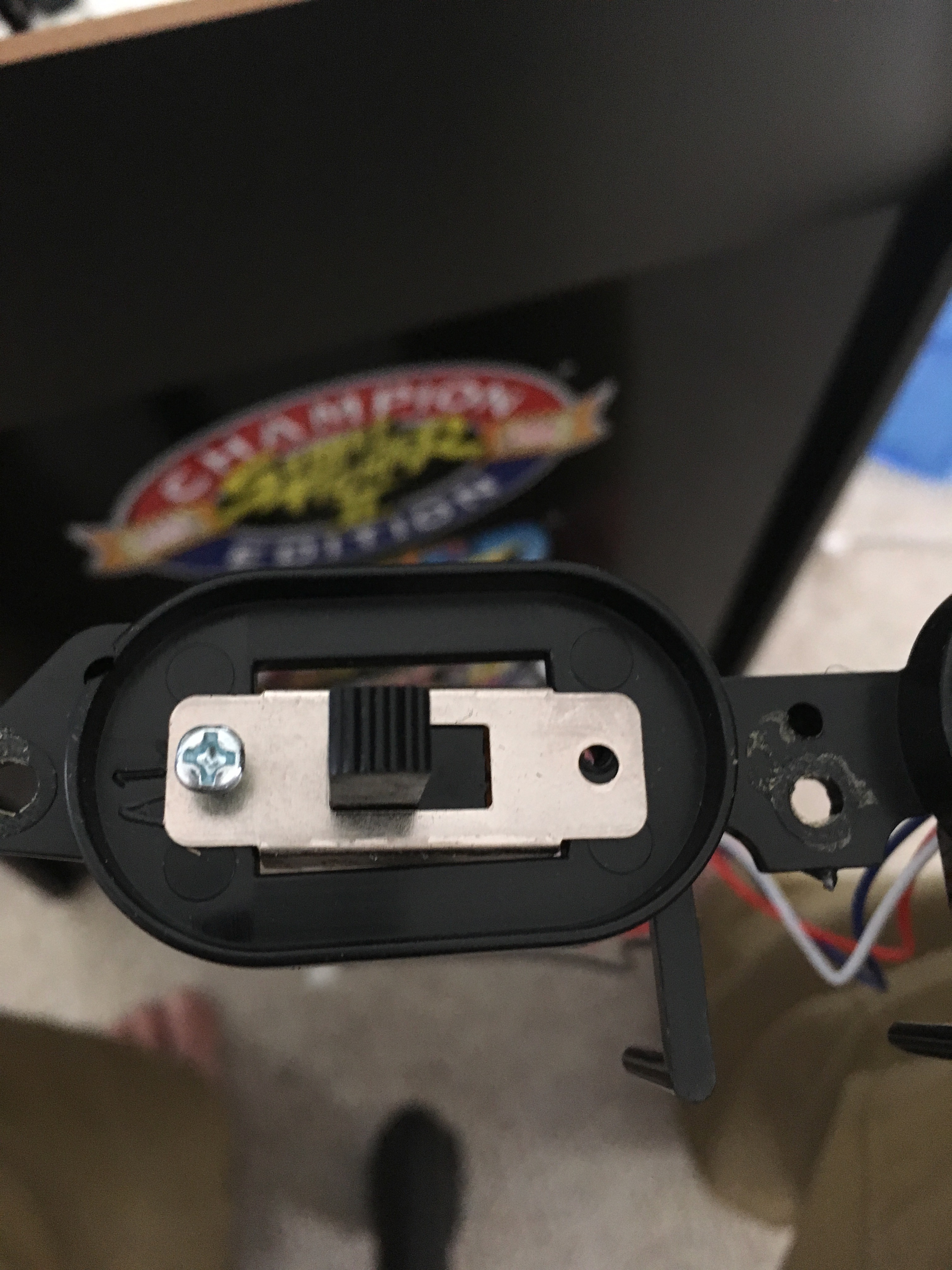
...and just rotate the switch around 180 degrees. Screw it all back together. Now your switch looks just like it did before, but On and Off map correctly to what the Pi wants and what the labels show.
Final caveat: if you cut the power to the Pi by unplugging it, when you plug it back in it will boot regardless of the GPIO pin state. In this case, you might have to toggle it On and then Off to acutally shut it down, but this is not a big deal.
Volume Switch
Here's the volume switch:
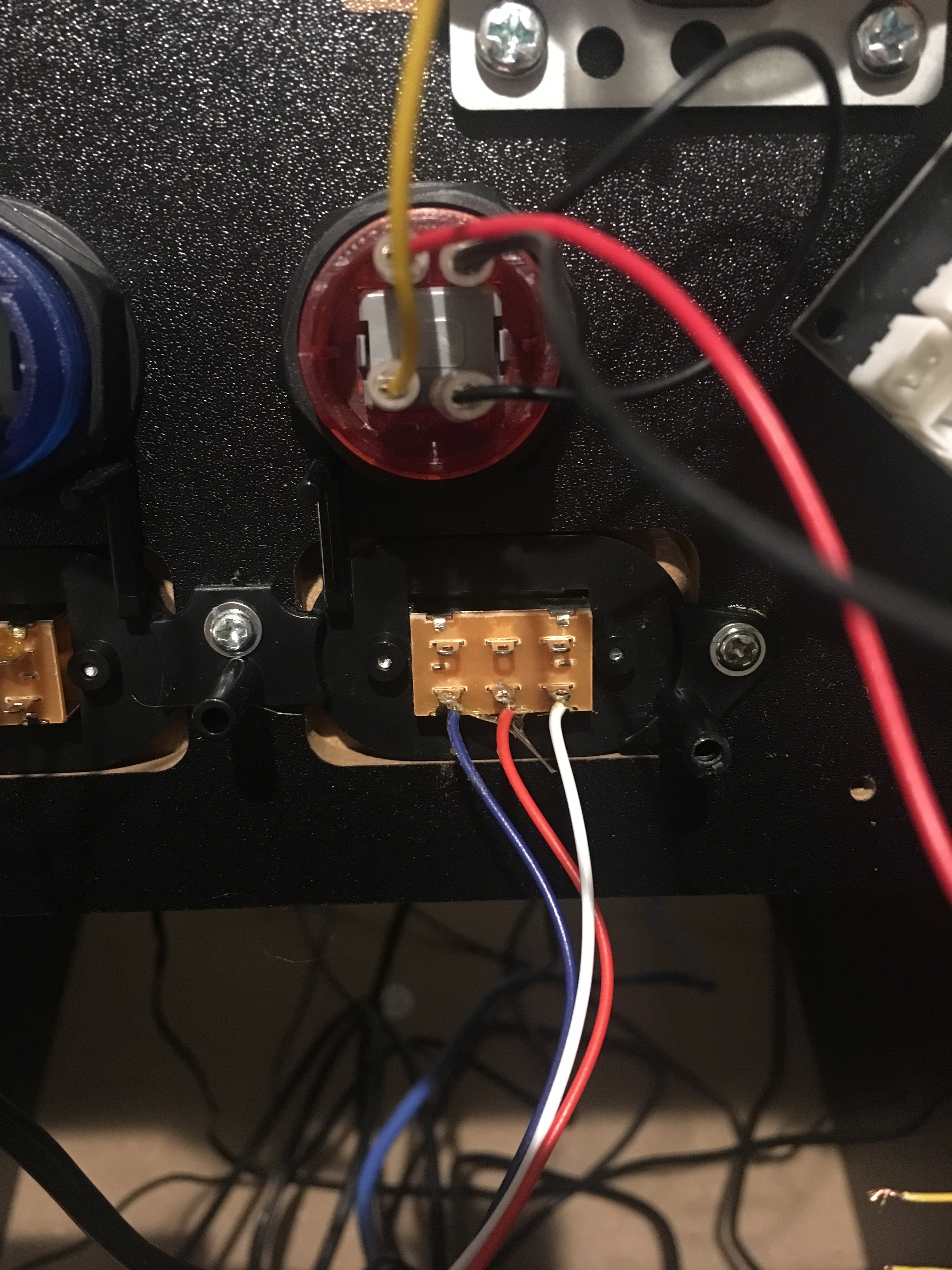
This one has three wires! The switch has three states (mute, quiet, loud), which we can represent with two wires (off/off, on/off, off/on), with that third wire being a ground wire the other two share.
This one is more complicated than the power button, partially because handling the switch's input isn't automated by that dtoverlay magic thing.
Fortunately, the wiring itself isn't hard. This one is going to need two GPIO pins and a ground pin, which luckily we have on the Pi, ordered so you can even use the existing connector as-is.
I wired this up to pins 12, 14, and 16 (which goes GPIO/Ground/GPIO, like the original connector is ordered). There are other groups of GPIO/Ground/GPIO on here; I skipped pins 7/9/11 because they're right next to the power pins we already used and both connectors can't fit that close together. Feel free to adjust if you have other wild Frankenstein plans for these pins, though! I won't judge.
The blue wire goes on pin 16, red on 12, and white on 14:
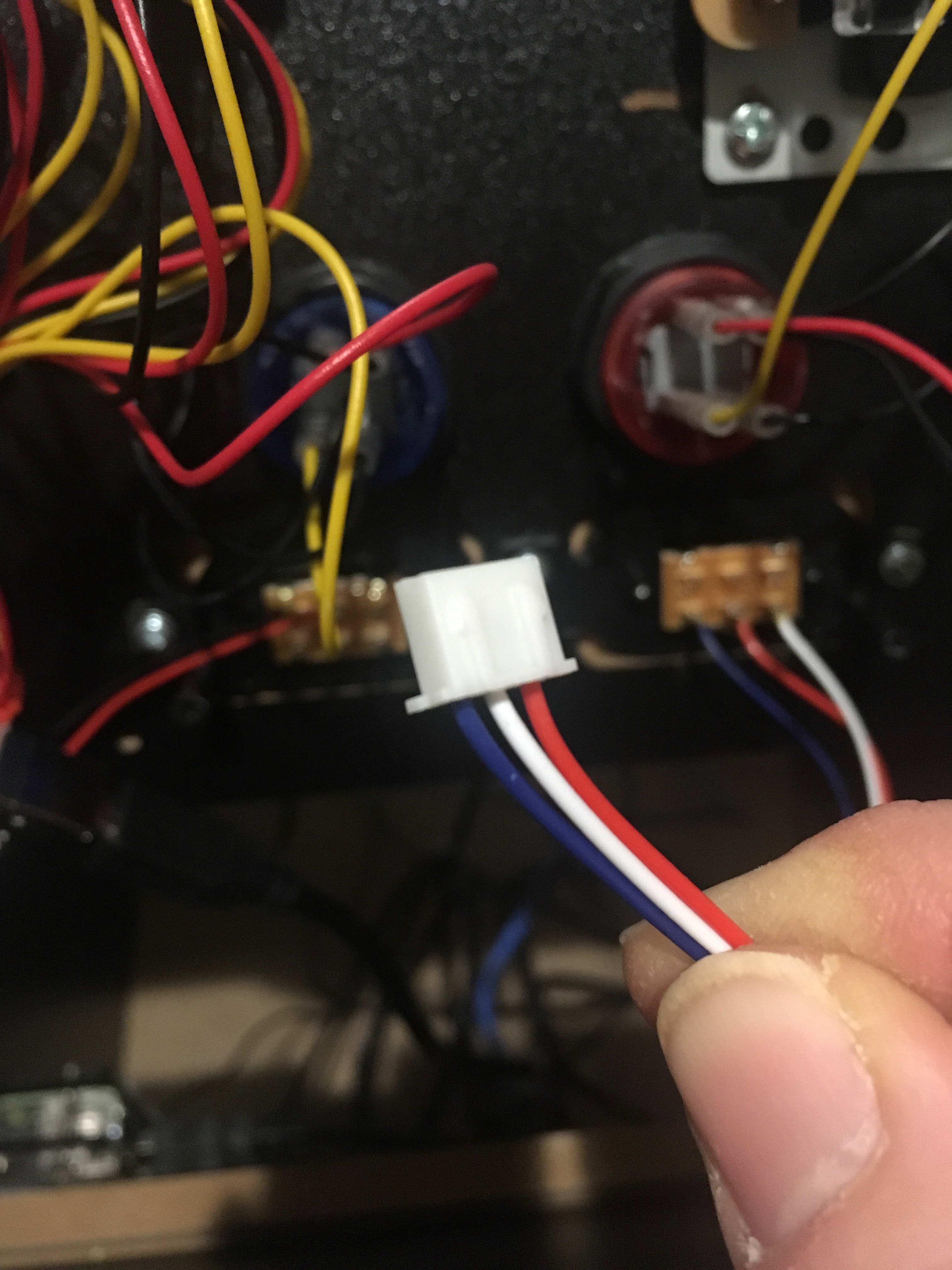
I don't have a picture of it connected, because I stupidly broke the original connector and replaced it (with a leftover wire from my replacement joystick buttons, like a boss! Like a boss that works at 1am in a world where Radio Shack folded years ago anyhow). Here's what it looks like if you don't care if the colors match up to what you have, so you know if you plugged it into the right place:
(White connector in that shot is the power switch, red one is the volume. Again: this is not the original connector that came with the cabinet!)
Everything around this is GPIO or Ground, so if you miss, it won't work but it (probably) won't fry the hardware. Don't miss, though!
Once that's plugged in, you need a program to listen for changes on those pins and do something in response. Everyone writes Python for this, but come on, what a waste. Use this C program I wrote instead:
// this is sort of a C equivalent of:
//  https://github.com/dmanlfc/arcade1up/blob/master/volume.py

// But this C code is public domain.  --ryan.

#include <stdio.h>
#include <stdlib.h>
#include <unistd.h>
#include <wiringPi.h>

int main(int argc, char **argv)
{
    int volumeState = 999;   /* force volume to be set at startup */

    wiringPiSetupPhys();

    pullUpDnControl(12, PUD_UP);
    pullUpDnControl(16, PUD_DOWN);

    while (1) {
        const int buttonState1 = digitalRead(12);
        const int buttonState2 = digitalRead(16);

        if (!buttonState1 && !buttonState2 && (volumeState != 96)) {
            printf("Switch was set to Vol HIGH (volstate %d => 96)\n", volumeState);
            system("amixer set PCM unmute");
            system("amixer set PCM 96%");
            volumeState = 96;
        } else if (buttonState1 && buttonState2 && (volumeState != 0)) {
            printf("Switch was set to MUTE (volstate %d => 0)\n", volumeState);
            system("amixer set PCM mute");
            volumeState = 0;
        } else if (buttonState1 && !buttonState2 && (volumeState != 75)) {
            printf("Switch was set to Vol LOW (volstate %d => 75)\n", volumeState);
            system("amixer set PCM unmute");
            system("amixer set PCM 75%");
            volumeState = 75;
        } else {
            usleep(300 * 1000);
        }
    }

    return 0;
}

// end of arcade1up-volume-gpio.c ...
You'll need to install WiringPi on the device...
sudo apt-get install wiringpi
...and then compile my program...
gcc -o arcade1up-volume-gpio -Os -s arcade1up-volume-gpio.c -lwiringPi
...if that all worked, just run it and see what happens. It should spit out some text each time you toggle the volume switch. Start a game that makes some noise and see if the volume adjusts between silent, quiet, and loud.
Is it working? Cool. Add this to the end of your Pi's /etc/rc.local ...
/home/pi/arcade1up-volume-gpio >/dev/null 2>/dev/null &
(or wherever you put the thing you compiled. I just left it in the default home directory.)
Reboot the machine. Now the volume switch should Just Work.
Adjust your amp to the loudest volume you ever want to hear out of this machine and never touch it again. The switch will go between silencing the machine, a reasonably volume (75% of loudest), and the loudest. Feel free to mess with the values in the C program and your amp if you want the switch to adjust a little differently.
If your switch is working backwards, flip the connector on the Pi around.
Ta-da...!
And that's it! Now you don't have to stare at these switches you're stuck with that don't do anything. Did I get anything wrong? Let me know and I'll update this post!
--ryan.