Neverball Mapping

Neverball environments are defined using GtkRadiant. Knowledge of GtkRadiant is prerequisite to this document. Users unfamiliar with radiant usage are encouraged to study the radiant documentation and craft a few maps for Quake, Wolf, etc, before attempting to create content for Neverball.

GtkRadiant, documentation, and tutorials may be found at

http://www.qeradiant.com

Contents

Overview
How Neverball compares to Quake et al
Setting Up
Getting GtkRadiant to work with Neverball
Tutorial
The map compilation process
Entities
Adding active elements to the map
Adding Materials
Creating custom textures and materials
Level Shots
Snapping screen-shots for level selection
Details
The different between a good level and a bad level

Overview

So now that we all know everything about Quake engine mapping, we can go ahead and forget most of it. Neverball mapping has significantly fewer restrictions than Quake mapping.

Some of the important differences are as follows:


Setting Up

Most any version of radiant will suffice. To install radiant, you will need to have one of the supported games installed. Demos MAY suffice. For this discussion, we assume that Quake 3 Arena is installed, and that it is located in

/usr/local/games/quake3/

We assume that Neverball data directory is

~/neverball/data

This may change depending on how Neverball is installed.

We must first make radiant aware of the Neverball materials. Under Linux, we can simply create a symbolic link from within the Quake data directory to the within Neverball data directory.

cd /usr/local/quake3/baseq3/
ln -s ~/neverball/data/mtrl             textures/mtrl
ln -s ~/neverball/data/mtrl/mtrl.shader scripts/mtrl.shader

Setup under Windows is similar, though it may be necessary to copy the mtrl directory and mtrl.shader script into the Quake directory, rather than use a shortcut.

Now, the mtrl shaders should appear in radiant's Textures menu. You may need to set "shaderlist.txt only" to OFF in the radiant Textures menu. Be sure that ONLY mtrl shaders are used for Neverball maps.


Tutorial

Here we gloss over all the details and try to get custom geometry into the game a quickly as possible.

Go ahead and create a simple map. Just toss in some brushes and plop some mtrl shaders down on them. Forget the entities for now, except drop in one info_player_start. Save the map anywhere.

Assume the map is named funkyball.map. Process it into a .sol with the following command. The first item specified is the input .map, the second gives the location of the mtrl directory. Output should be similar.

mapc funkyball.map ~/neverball/data

  mtrl  vert  edge  side  texc  geom  lump  path  node
    10   552  1086   130   277   854   132     0    33
  body  coin  goal  view  jump  swch  ball  char  indx
     1    18     1     1     0     0     1    84  4286   115

To test your map, add it to a data/levels.txt file. Use the existing level entries as a guide. Include a level shot path, a background path, and the level time in seconds. Paths in levels.txt are relative to the data directory (the location of levels.txt). Then, run the game as normal.


Entities

Only a few Quake entities are supported, and most of the supported entities behave differently in some way. All unsupported entities and unsupported attributes of supported entities are ignored. The Neverball entities follow. All applicable entity attributes are documented here.

info_player_start

The info_player_start entity defines a ball in a .sol file. While multiple balls may be defined, Neverball uses only the first of them.

The "radius" attribute gives the ball radius in meters. The default radius is "0.25".

The "origin" attribute gives the ball location. The bottom of the entity in the editor will correspond to the bottom of the ball in Neverball.

Note that the "angle" attribute does NOT determine the initial facing direction. The player begins each level looking down the Y axis. If your level begins wrong, you must rotate your map.

info_player_deathmatch

The info_player_deathmatch entity defines a goal in a .sol file. The "radius" attribute gives the goal radius in meters. The default radius is "0.75". The ball must fall entirely within this radius to trigger a goal.

The "origin" attribute gives the goal location. Like the ball entity, the bottom of the editor's entity box will correspond to the base of the goal.

light

The light entity defines a coin in a .sol file. The "light" attribute gives the value of the coin. Neverball draws coins in denominations of 1, 5, and 10.

The "origin" attribute gives the coin location. Consider the radius of your ball and place coins within reach from the floor.

path_corner

The path_corner entity defines a segment of the path of a moving object. The "origin" attribute gives the point location.

The "targetname" attribute gives the name by which other entities will refer to this point. The default name generated by radiant is usually fine.

The "target" attribute gives the destination of the path. This attribute may be automatically specified using radiant's "Connect Entities" feature. To make a path from point A to point B, first select path_corner A, then select path_corner B, then Connect Entities (control-k).

The "speed" attribute gives the duration of the trip along this path segment. Note that this attribute has a different meaning to Neverball than it does to Quake. In Quake, it gives the speed in units per second. In Neverball it gives the travel time in seconds, regardless of the distance between one point and the next. The default is "1.0".

The "state" attribute determines whether the path is enabled. A func_train will only move along an enabled path. A train may be stopped and started by toggling the state of the path to which it is attached. "0" means no, "1" means yes. The default is 1.

To create a pause in a path. Simply position two connected path_corner entities at the same point. The trip will have zero length but the object will still spend "speed" seconds making the journey.

func_train

The func_train entity defines the geometry of a moving object. Think of it as a container or a grouping mechanism for lumps, rather than an object in-and-of itself.

To create a func_train, first select all of the brushes that form the moving object, then select func_train from the entities pop-up (right click) menu.

To assign a func_train to a path, first select the func_train, then select the first path_corner entity of the path, then Connect Entities. Multiple func_trains may be assigned to one path.

To destroy a func_train leaving only the original brushes, select the func_train, and choose Ungroup Entities from the Selection menu.

Note that func_trains are positioned differently in Neverball than in Quake. Quake ignores the placement of the func_train in space and requires an origin specification. Neverball simply uses the location of the first path_corner to define the origin. When creating a moving object, just place it at the beginning of its path and everything should work out.

The "model" attribute of the func_train entity may be used to attach an arbitrary polygonal model to a moving object. See the discussion of the misc_model entity, below.

target_teleporter

The target_teleporter entity defines a teleporter. The "radius" attribute gives the teleporter radius. The default is "0.5". The ball must fall entirely within this radius to trigger the teleport.

The "origin" attribute gives the teleporter location. Unlike the goal entity, the center of the editor's entity box defines the origin. So to define a teleporter flush with the floor, embed the entity box halfway in the floor.

The "target" attribute refers to a target_position entity defining the destination of the teleporter.

info_camp

The info_camp entity defines a switch. A switch's behavior is similar to a teleporter. The "radius" attribute gives the radius and defaults to "0.5". The "origin" attribute gives the location. The "target" attribute refers to the path_corner that the switch controls.

The "state" attribute gives the initial state of the switch. "0" is off, "1" is on. The default is off. This parallels the state attribute of the path_corner. An info_camp entity should always have the same initial "state" value as the path_corner it targets.

The "timer" attribute defines a delay time. The time begins when a switch is toggled to its non-initial state. The switch toggles back to its initial state when the timer expires. A timer value of zero indicates an UN-timed switch. The default is zero. This may be used to define a door that opens only for a moment before closing, or a func_train that moves along its path in discrete activated steps.

info_player_intermission

The info_player_intermission entity defines the camera position at the beginning of a level fly-in. The "origin" attribute gives the location, and the "target" attribute refers to the target_position defining the view direction.

target_position

The target_position entity defines the initial view direction of a level fly-in, as well as the destination of a teleporter. The "origin" attribute gives the location. To define a two-way pair of teleporters, place the target_position of each coincident with the target_teleporter of the other.

misc_model

The misc_model entity imports an arbitrary polygonal model into a level. It may be used to increase the visual detail of a level without increasing the physical detail. Arbitrary normal vectors are allowed, so the misc_model entity can be used to produce smoothly shaded curves.

Misc_model entities define visible geometry, but not physical geometry. So, if the ball is to bounce off of a misc_model entity, the entity should be placed within one or more invisible structural lumps.

The "model" attribute gives the filename of the model relative to the data directory. The model must be in OBJ format. It must have triangular tesselation. All vertices must have normals and texture coordinates. The author uses Wings3d to create and export OBJ models.

The "origin" attribute defines the position of the model.

worldspawn

The worldspawn entity is the root of the world. The "message" attribute gives the intro text that appears as a level begins. A '\' character in the text marks the end of a line. Limited space is available. Wrapping text within the intro text box is often a process of trial and error.

Radiant's text edit box may or may not provide all the editing capability you need. In particular, if you want to add accented characters to a level's intro text, you may need to load the .map file using a text editor, and edit the message by hand.


Adding Materials

Neverball uses the standard OpenGL lighting model rather than a script-based shading system like Quake's. So, to add a new material you must create both a texture image and an OpenGL material specification.

  1. The texture must be an image in either JPG or TGA format. In general, use TGA for images that require an alpha channel, and JPG otherwise. Image width and height must both be powers of two. For this discussion, let us assume you have an image named wood.jpg. Place in it mtrl/.
  2. Create a material file in mtrl/, in this case mtrl/wood. This name must match the texture name, minus the image suffix. The file must contain 18 values, explained below. If you don't care about the material properties, the following values suffice in most any case.

        1.0 1.0 1.0 1.0
        1.0 1.0 1.0 1.0
        0.2 0.2 0.2 1.0
        0.0 0.0 0.0 1.0
        0.0
        1
        

Do a "Flush & Reload Shaders" in radiant and your new material should appear among the mtrl shaders.

Those 18 values define the material in terms of the standard OpenGL material model. They define not only the color of the material, but how it reacts to different types of lighting and different points of view. Their meaning is a follows:

  1. The first line gives the diffuse material color (R G B A). This is the basic color of the material resulting from directional light falling upon it. The fourth component is the alpha channel. 0 is transparent, 1 is opaque.
  2. The second line gives the ambient material color. It gives the color of the material resulting from non-directional light. It doesn't make much of a contribution in practice.
  3. The third line gives the specular material color. This is the color of the material when directional light is glinting directly off of it into the eye of the user. A bright white here will make an object look shiny, while a darker color will give the object a matte appearance.
  4. The fourth line gives the emissive material color. This color contributes to the appearance of the object regardless of the light falling upon it. A bright color here will make an object appear to glow in darkness, or at least appear to be unaffected by external light.
  5. The fifth line gives the material shininess. Simply put, it defines the size of the specularity on an object. 0 will produce a dull finish, while 128 will produce a very tight specularity.
  6. The sixth line gives the material type. 1 is a normal opaque surface. 2 is a transparent or translucent surface. 4 is a reflective surface. 8 is an environment-mapped surface. Multiple material types may be ORed, though the results are unlikely to be useful. See the below for restrictions related to transparent and reflective surfaces.

The five of these together determine the base color of the material. This base color is then blended with (added to) the texture color.


Level Shots

A level shot is a screen-shot of a level without the ball or any coins visible. It is used to preview a level in the level selection screen. Level shots are listed along with their SOL files, background files, etc in the levels.txt file. There are two ways to acquire a level shot: per level, and per set.

To acquire a single level shot, press F12 at the level's intro screen. This will clear the HUD and all entities. Then, press F10 to take a screen-shot normally. Rename the screen-shot as needed and prepare it as described below.

To capture level shots for an entire set, go to the set's selection screen and press F12. This will iterate through all levels and automatically take a screen-shot of each. The resulting BMP files will have the same name as the source SOL file as listed in the levels.txt file.

NOTE: If the SOL file has the name "sol/foo.sol" then the resulting screen-shot will have the name "sol/foo.bmp". Thus, if your normal screen-shot directory is your home directory, you must ensure that $(HOME)/sol exists and that the level shots may be written there.

To be usable in level selection, a level shot must have power-of-two size. Screen-shots generally don't, thus they must be non-uniformly scaled. 256x256 is usually a good choice. JPG is usually a good format, as it is compact. Both the size and format of the image are optional.

The author uses the following ImageMagick command line to convert an entire set of level shots to JPG.

mogrify -resize 256x256! -format jpg -quality 80 *.bmp

Details

There is a lot more to a Neverball map than a collection of lumps and entities. The quirks and details of Neverball mapping are not obvious. They are generally only learned through experience. Many players have submitted maps, and pretty much everyone consistently makes the same mistakes. The following sections describe these mistakes, and lay down guidelines that should be followed during map creation. These are what separate a good map from a bad map.

Physics

The Neverball physics engine can take pretty much anything you throw at it without breaking down, but there are a few problem areas.

If a ball gets squished by a moving object, it will probably end up moving into and through a solid, possibly getting stuck there. There's just no easy solution to this problem. The physical analogue would be to have the offending moving object stop moving. But then what? Nothing moves, nothing changes, and the problem certainly doesn't resolve itself.

Currently, the best solution is to stick with the unreal behavior. At least it keeps things moving. Mappers should actively avoid creating situations in which this unreal behavior is made apparent.

  • If you have an elevator moving up and down, prevent the ball from standing underneath. Either make the elevator shaft a solid (potentially invisible) object, or make it a bottomless pit.
  • If you have platforms moving horizontally, for example a ferry across a gap, ensure that a ball falling off the platform into the gap falls all the way out of the platform's path by making the gap deep.
  • If you have a Quake-ish crusher, delete it. There's just no place for something like that in Neverball because the ball doesn't "die", it merely falls.

Finally, try to keep your lump counts in a reasonable range. In the mapc output, the lump count is the last number on the last line. In this example, the number of structural lumps is 115.

  mtrl  vert  edge  side  texc  geom  lump  path  node
    10   552  1086   130   277   854   132     0    33
  body  coin  goal  view  jump  swch  ball  char  indx
     1    18     1     1     0     0     1    84  4286   115

A map with many lumps requires greater processing power in-game. If a map has too many lumps, then players with older hardware will not be able to play it. In the default map set, the most complex level has 585 structural lumps. This is probably too many. Try to keep it under 500.

Z-Fighting

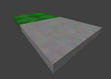
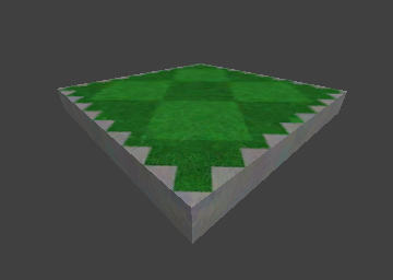
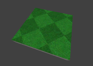
Z-Fighting is one of the most basic mistakes you can make, yet people do it all the time. It occurs when two textured surfaces coincide. The Z-buffer usually indicates which surface is in front, and allows only that one to be visible. However, when surfaces coincide, numerical precision errors crop up. The answer to the question "Who is in front?" is not guaranteed to be consistent across the entire surface.

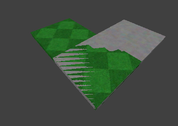
Here, the top surfaces of the green and grey lumps are coincident.

T-Intersections

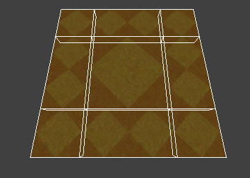
T-intersections are another really common mistake. The meaning of the term "T-intersection" should be pretty obvious from the image below. It is an instance where a vertex of one lump falls along the edge of another lump.

T-intersections are bad because they can result in "polygon cracking", or single pixels of background color that seem to shimmer randomly along the edge in question. This occurs because edges are drawn as linear interpolations between vertices. Even thought vertices may be co-linear, there is no numerical guarantee that every pixel in the linear interpolation between one pair of vertices will coincide with the pixels of the interpolation between another pair. Those pixels where the interpolation does not coincide appear as cracks.

Ensuring that a map has no T-intersections often requires planning and forethought. After you've decided how a surface should be shaped and how textures should be laid out on it, it is often a puzzle to determine how this shape should be subdivided into lumps. An intersection-free map often has many more lumps than the same map would otherwise have, but a clean map is worth the extra geometry.

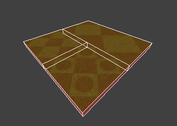
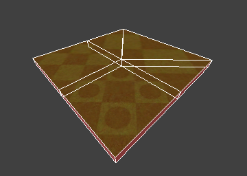
This is a surface with 3 textures. First with a T-intersection, second with the T-intersection removed.

"Caulking"

Quake engine mappers are certainly aware of the notion of caulking. Caulking involves marking the surfaces that the user will never see as invisible. In normal Quake editing, this is done by setting the surface texture to a bright pink texture named "caulk". In Neverball, we use a white grid texture called "invisible".

The invisible texture should be used anywhere two lumps are placed side to side. There is no circumstance under which the player will see the faces between the lumps, so it is inefficient to render them. By marking them as invisible, you improve the efficiency of your map, and therefore the performance of the game.

In fact, the author starts out by selecting ALL lumps and applying the invisible texture globally. He then goes back and re-textures only the visible sides. Perhaps this is a bit extreme, but it guarantees that all unseen sides will be marked invisible.

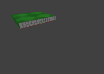
Here, the near side of the green lump is caulked, because the grey lump prevents it from ever being seen.

Detail Lumps

There are many occasions where the mapper may want to define geometry that be seen, but that does not affect the ball. This is called detail geometry.

Detail lumps have two major uses. One is the application of decal textures, discussed below. The other is performance. If you define visual entities that the ball can never touch in normal game-play, you should mark them detail. The physics code will then be able to ignore these lumps and the game will perform better.

Lumps may be marked as detail by selecting the "Selection / Make Detail" menu option in radiant. Detail lumps are returned to normal with "Selection / Make Structural".

Decals

There are a number of occasions where you'll want to apply one texture over-top another. Examples include goals, jumps, switches, and arrows. It's common to have a goal texture appearing in green turf, or red turf, etc, but it is inefficient to use a different texture map for each ground/decal combination.

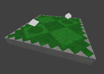
To accomplish this, we apply the decal texture just above the base texture using a second lump. Mark the top of this lump with the decal texture and mark the other 5 sides with the invisible texture.

Position the decal lump 1 unit above the base lump. Do not position the top of the decal lump coincident with the base lump, as this will cause Z-fighting.

Very important: mark the decal lump as detail using the "Make Detail" menu item. If the decal lump is allowed to be structural then the ball will bump into it, as it is 1/64th of a meter from the floor.

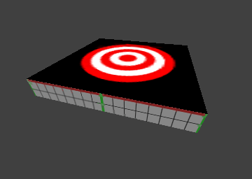
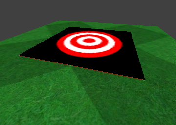
This is a decal lump by itself, and the same decal lump with the surface lump to which it is applied.

Mitering

Mitering is a common technique for joining lumps at corners. It simply involves cutting lumps at 45 degree angles, as in a wooden picture frame. It has the effect of reducing T-intersections, while minimizing lump counts.

Mitering is most useful when you're trying to work your way around a non-trivial texture layout, as in the example below.

Mitres can be created using radiant's edge editing tool (press 'e' to enable) or clipping tool (press 'x' to enable). See the radiant documentation for the details of these functions.

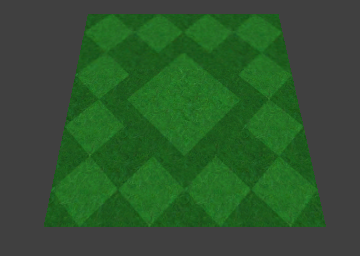
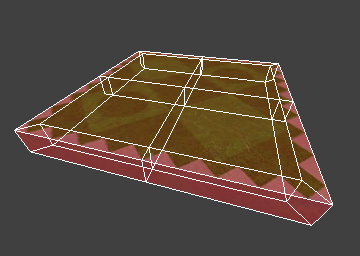
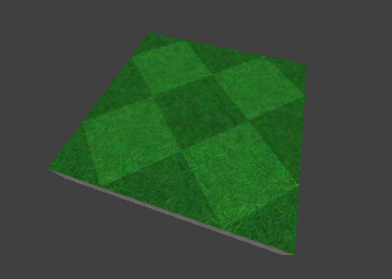
This is our desired texture layout, a large diamond surrounded by small diamonds.

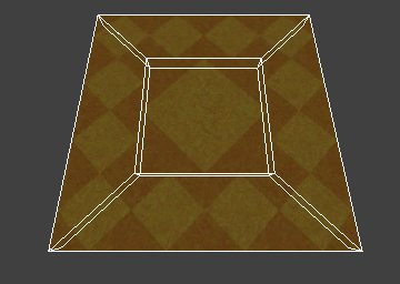
The unmitered map uses 9 lumps, while the mitered map yields the exact same texture layout using only 5 lumps.

Trimming

Interesting texturing is important to the overall visual appeal of a level, and it doesn't really take much effort or thought at all. New mappers often think more about their geometry than their textures. They design a level and just plunk down some arbitrary materials. It looks like this:

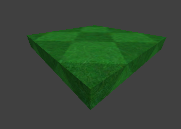
At the very least make sure the side texture differs from the surface texture, just to accentuate the discontinuity.

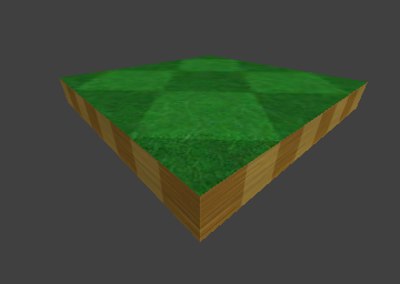
Better yet, invest a few extra lumps trimming your surfaces. Each of the default surfaces textures has a corresponding trim texture. Trimming has the effect of pointing out the edge of a surface, while adding an amount of visual appeal through simple variety.

The visual impact there is not of a green object, but of a stone or concrete object with turf applied to the top.

Coin Padding

A coin pad is a special surface texture that indicates the presence of a coin. Coin pads are not absolutely necessary, but they add a great deal of variety and visual appeal, and they contribute strongly to the appearance of polish and finish in a level.

Coin padding will almost certainly increase the complexity of the layout of a surface. Proper padding may require some creative lumping and mitering in order to keep T-intersections from cropping up. However in the end, the extra complexity pays off.

Texture alignment and sizing

The size and tile pattern of each texture implies a default placement and a style of usage. The implied usage of each texture should be recognized and exploited at every opportunity.

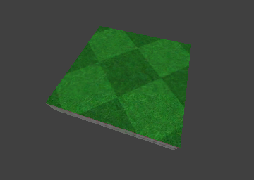
For example, a 256x256 texture, such as the large green diamond, is 2 meters wide in-game, thus it is appropriate for use in tiling objects that are a multiple of 2 meters in size. Likewise, the small green diamond texture repeats every 128 pixels, and is appropriate for tiling 1-meter objects.

Of course these rules are not enforced. But if textures are applied in the manner in which they "want" to be applied, then they work together much better.

Here, a texture is applied to an object that is a bit too small. The repeating pattern is cut off. If trimming were added, or another texture applied to an adjacent lump, there would be an obvious discontinuity.

Here, the object is sized properly, but it does not fall along a 1-meter grid line. Thus, the texture is misaligned. This problem may be solved on a surface-by-surface basis using radiant's surface editor. However it is usually easiest just to align objects along the default texture lines. If a group of surfaces are not consistently aligned, another discontinuity will appear.

Here, a 2-meter object is aligned to the 1-meter grid. The texture lays naturally across it, and the mapper need not do anything different.

A user playing the game will probably not notice the difference if a platform is 2 meters wide instead of 1.8 meters wide. However, he WILL notice if a texture does not line up properly with its neighbors.

Reflective surfaces

Neverball supports a very limited form of reflective surface. A reflective surface must be defined with two properties. First, the surface must have a reflective material type, as defined in the material file. Second, the surface must be flat with a Z value of 0.

This means that reflection is limited to shiny flat floors. There can be no upright mirrors, or mirrors on ramps, or multiple levels of mirrors, or crazy halls of mirrors.

Mappers should keep in mind that heavy use of mirrors can kill performance on weaker hardware. However, the author doesn't give a damn. That's why he implemented the option to turn reflection off. All you crybabies can go buy a better video board.

Transparent surfaces

Neverball is capabable of correctly drawing transparent surfaces in most contexts. It does sort transparent objects correctly with respect to opaque objects. However, it does NOT sort transparent objects with respect to other transparent objects.

This means that if one is looking through a pane of class at a wall then the wall and the glass are guaranteed to be displayed correctly. But when looking through one pane of glass at another pane of glass, there is no guarantee that ether pane will be correctly rendered.

Mappers are advised to keep transparent objects to a minimum in order to avoid the inconsistencies that can result. It should be noted however that Mehdi flagrantly violates this rule in nearly every level he makes, and the author doesn't mind too much.

Curves

Neverball does not have any explicit support for curved surfaces. All of the curves in the default level set are made up of a large number of small planar lumps generated by the following program:

curve.c

The program takes 5 parameters. It sends its output to stdout, where it may be redirected to a file and loaded into radiant as a prefab.

./curve r0 r1 n a0 a1 > mycurve.map

Lumps are generated on the 1-unit grid. The granularity of this grid is a limiting factor. It allows large curves to be very smooth, but small curves must be coarse. Mappers interested in curved surfaces are advised to plan big. Curves are generated in the Z plane. They may be rotated as required.